Animal traps and trigger mechanisms

a technology of trigger mechanism and animal trap, which is applied in the field of animal traps, can solve the problems of reducing the efficiency of a pest control programme, unpractical, and unsatisfactory emptying of a trap

Active Publication Date: 2017-04-11
GOODNATURE LTD
View PDF19 Cites 6 Cited by
  • Summary
  • Abstract
  • Description
  • Claims
  • Application Information

AI Technical Summary

Problems solved by technology

These traps generally kill and retain an animal, and therefore require a user to empty and reset the trap.
Some users find emptying a trap disagreeable and in some circumstances it may not be practical or may reduce the efficiency of a pest control programme.
This requires significant labour, since rangers are required to walk the trap line clearing, re-setting and re-baiting the traps.
In addition, if a trap is triggered soon after being checked it will be out of action for most of the four week period.
That mechanism is unlikely to work well as it would require a significant force in order to be actuated and the time between movement of the trigger and actuation of the cage closing mechanism would be relatively long.
While this mechanism may be suitable for cage trap applications for relatively large pests, it is not well suited to kill-trap applications or to smaller or more cautious animals.

Method used


Image

  • Animal traps and trigger mechanisms
  • Animal traps and trigger mechanisms
  • Animal traps and trigger mechanisms

Examples


Embodiment Construction

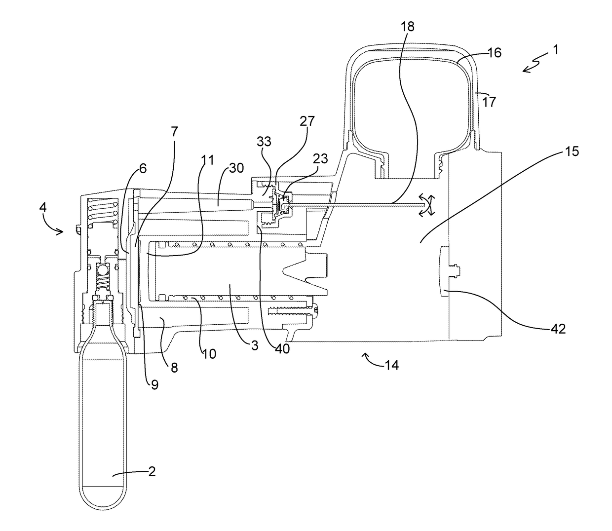
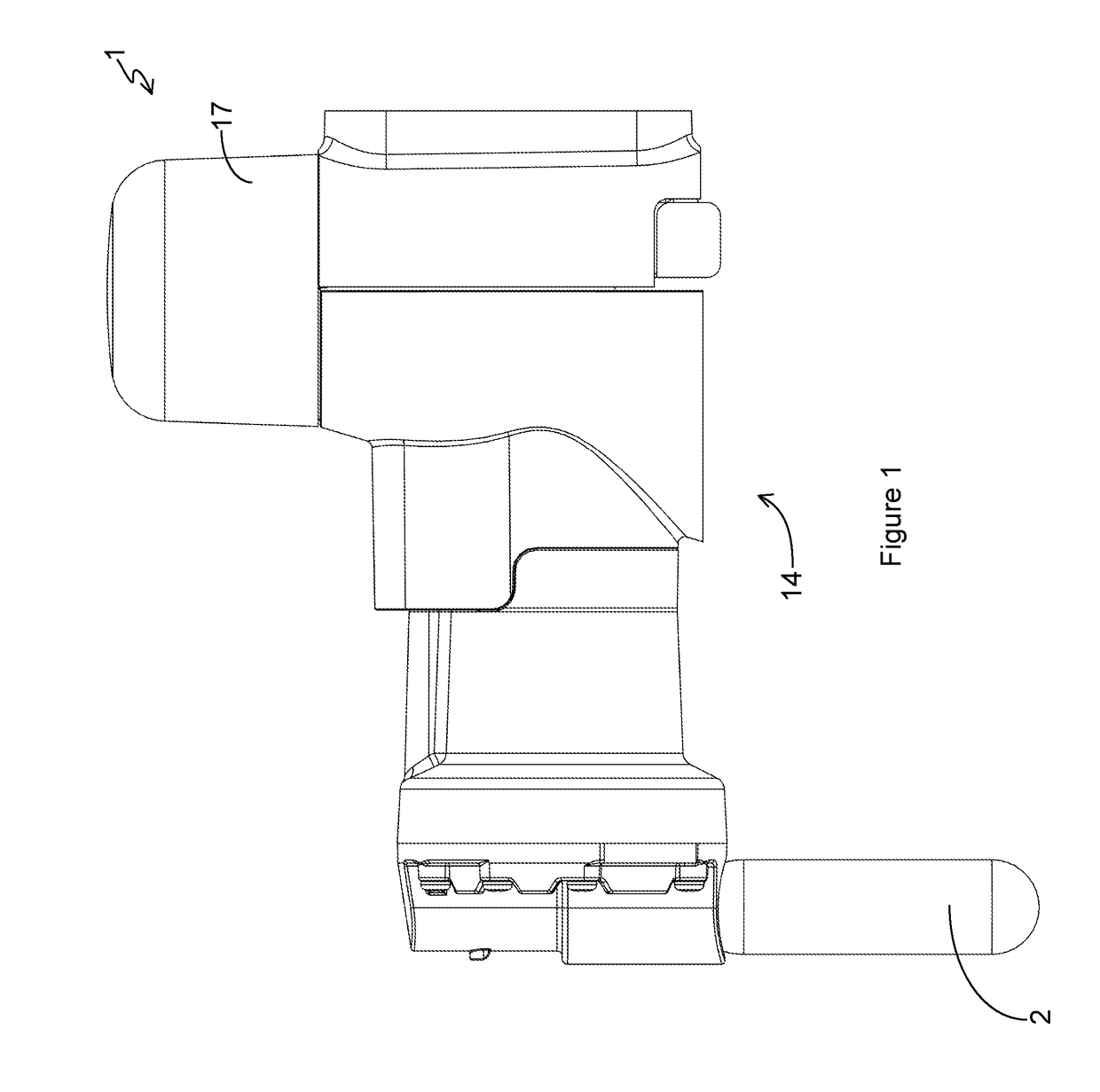
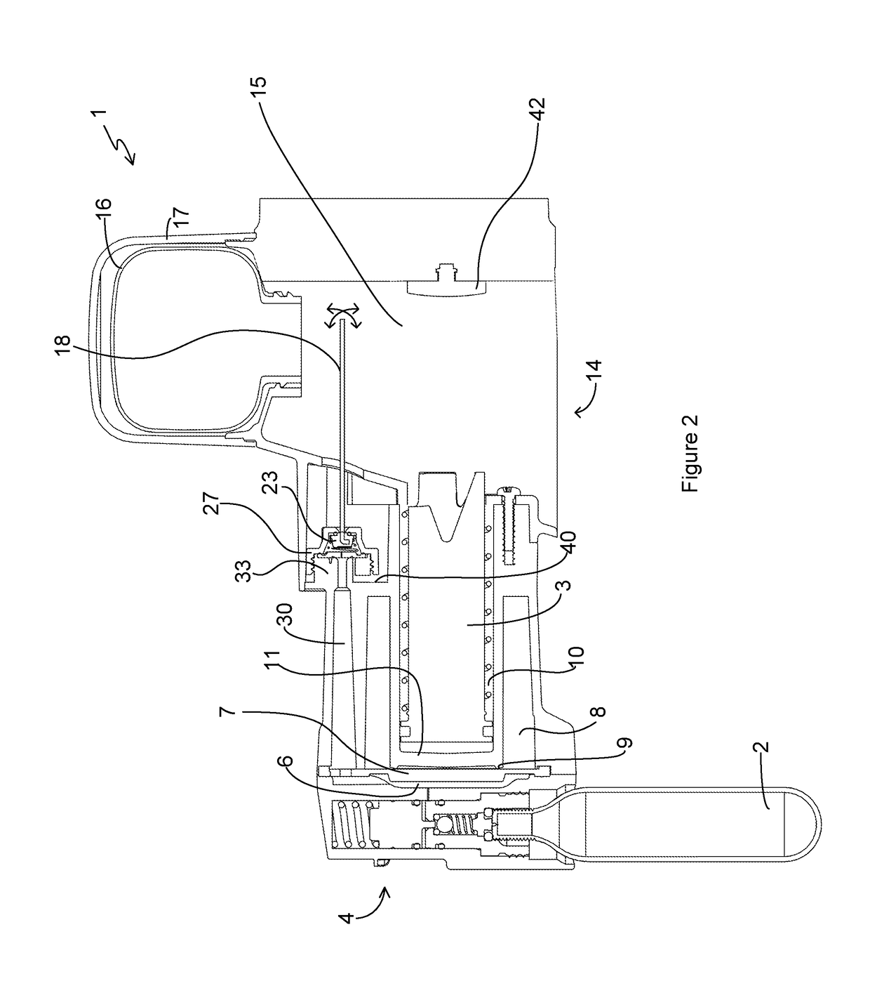
[0054]FIG. 1 is a side view, FIG. 2 is a cross-section and FIG. 3 is an exploded view of a trap 1 according to one embodiment. The trap 1 includes a source of compressed gas 2, in the embodiment shown as a canister. The trap 1 also includes a flow control arrangement (described in detail below) designed to control gas flow for operation of a kill mechanism 3 by compressed gas drawn from source 2. However, other power sources may be used in some embodiments, such as sources of electricity or mechanical power.

[0055]The source 2 of compressed gas may be a canister (such as a readily available CO2 canister), cylinder or any form of suitable reservoir for holding pressurised gas. The gas may be stored in a solid form within the source, being released from the source as a gas (as is the case with some CO2 canisters). Such canisters are easily replaced when empty or as part of a routine servicing of the trap. Other sources of compressed gas can be re-pressurised. For example, some reservoi...


PUM


Abstract

An animal trap may include a source of compressed gas; a trigger mechanism configured to be actuated by an animal, and a kill mechanism powered by compressed gas. The trap may include two or more trigger valves connected in series. At least one trigger valve may include an opening, a valve seat surrounding the opening, a valve member having a sealing surface, and an O-ring arranged to seal between the sealing surface and the valve seat. One or more flow paths may allow gas to flow along at least part of an internal periphery of the O-ring. The trigger may include a trigger rod extending in a rest position from a mount at or near a first end thereof. The trigger rod may be mounted for pivoting movement about the mount, and may have two rotational degrees of freedom. Pivoting movement of the trigger rod in any direction away from the rest position may result in actuation of the trigger.

Description

FIELD OF THE INVENTION[0001]The invention relates to animal traps, particularly but not exclusively to animal kill traps.BACKGROUND TO THE INVENTION[0002]Known animal traps generally include some form of trigger with a mechanical kill mechanism powered by a spring. Traps are used to kill various pests, including (in New Zealand) mice, rats, stoats, possums, hedgehogs, cats, weasels and ferrets. In other countries, other pests are of course present.[0003]Known traps generally include three types of trap. Cage traps capture animals alive and allow non target species to be released. Target species are killed by the trapper, which has the advantage that the animal's fur can be more easily removed while the animal is still warm. Leg hold and snare traps physically hold an animal by securely holding its leg. These traps also capture the animal alive and are much lighter and more compact than cage traps.[0004]The third type of trap is the kill trap, which automatically kills animals rather...

Claims


Application Information

Patent Timeline
Patent Type & Authority Patents(United States)
IPC IPC(8): A01M27/00A01M23/14A01M23/36
CPCA01M27/00A01M23/14A01M23/36
Inventor BOND, CRAIG RICHARDBARR, STUART WILLIAMVAN DAM, ROBERT BLAIR
Owner GOODNATURE LTD
Why Eureka
Try Eureka