Vehicle cooling arrangement

a cooling arrangement and vehicle technology, applied in the field of vehicles, can solve the problems of reducing the service life of the vehicle,

Active Publication Date: 2017-04-11
AGCO INT GMBH
View PDF13 Cites 2 Cited by
  • Summary
  • Abstract
  • Description
  • Claims
  • Application Information

AI Technical Summary

Problems solved by technology

Radiators in this arrangement, however can result in creating a high resistance to air flow.
The radiator arrangement may also interrupt the air flow resulting in overheating of the radiator or radiators.
The radiator sub-assembly is therefore subject to substantial restrictions with respect to its dimensions particularly in width and height.
Since the heat sink of the radiators cannot therefore be substantially increased, dissipation of the resultant waste heat presents difficulties, particularly because of the trend to constantly increase the drive power of the vehicle.
Such an arrangement does not optimise the air flow through the radiators and may necessitate a larger fan to obtain the desired air flow.

Method used


Image

  • Vehicle cooling arrangement
  • Vehicle cooling arrangement
  • Vehicle cooling arrangement

Examples


Embodiment Construction

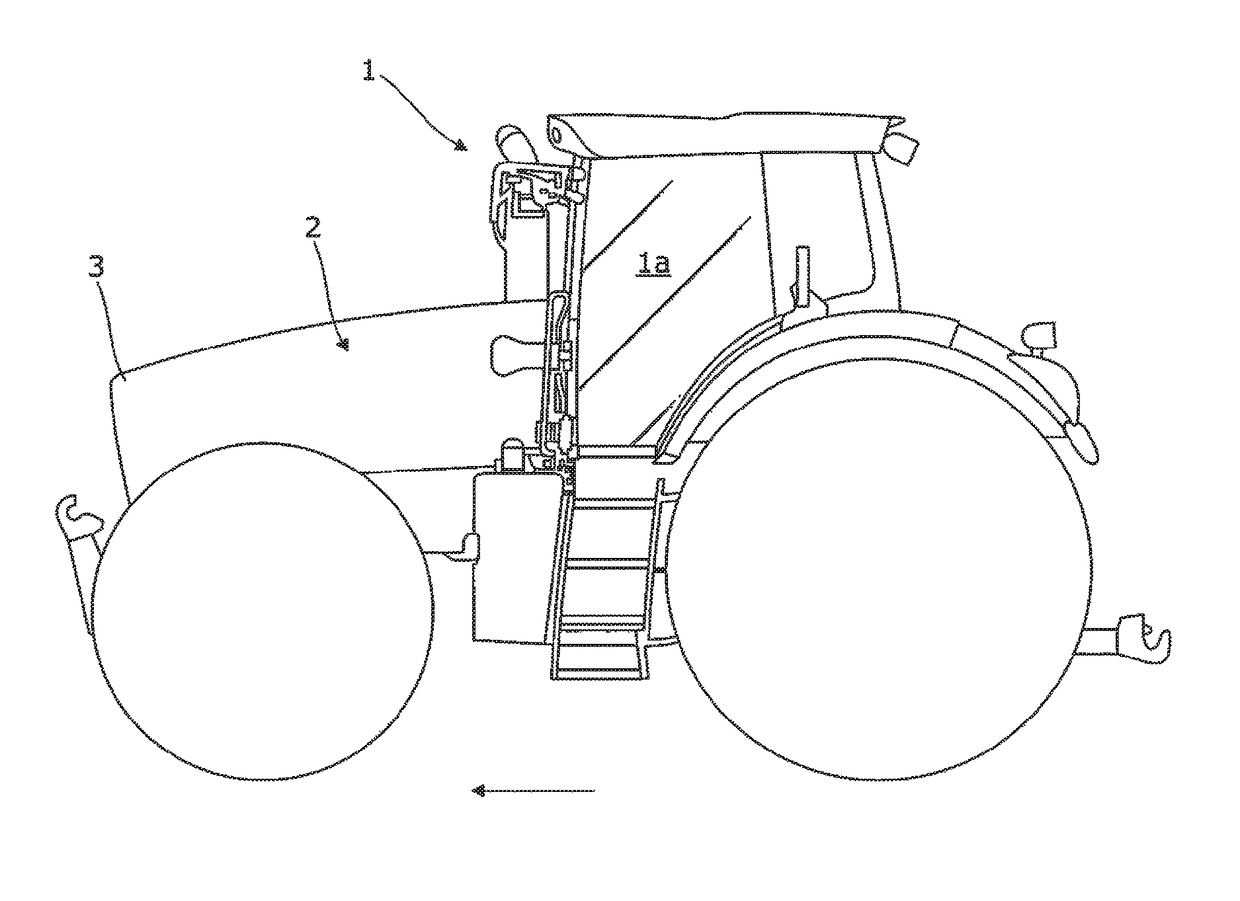
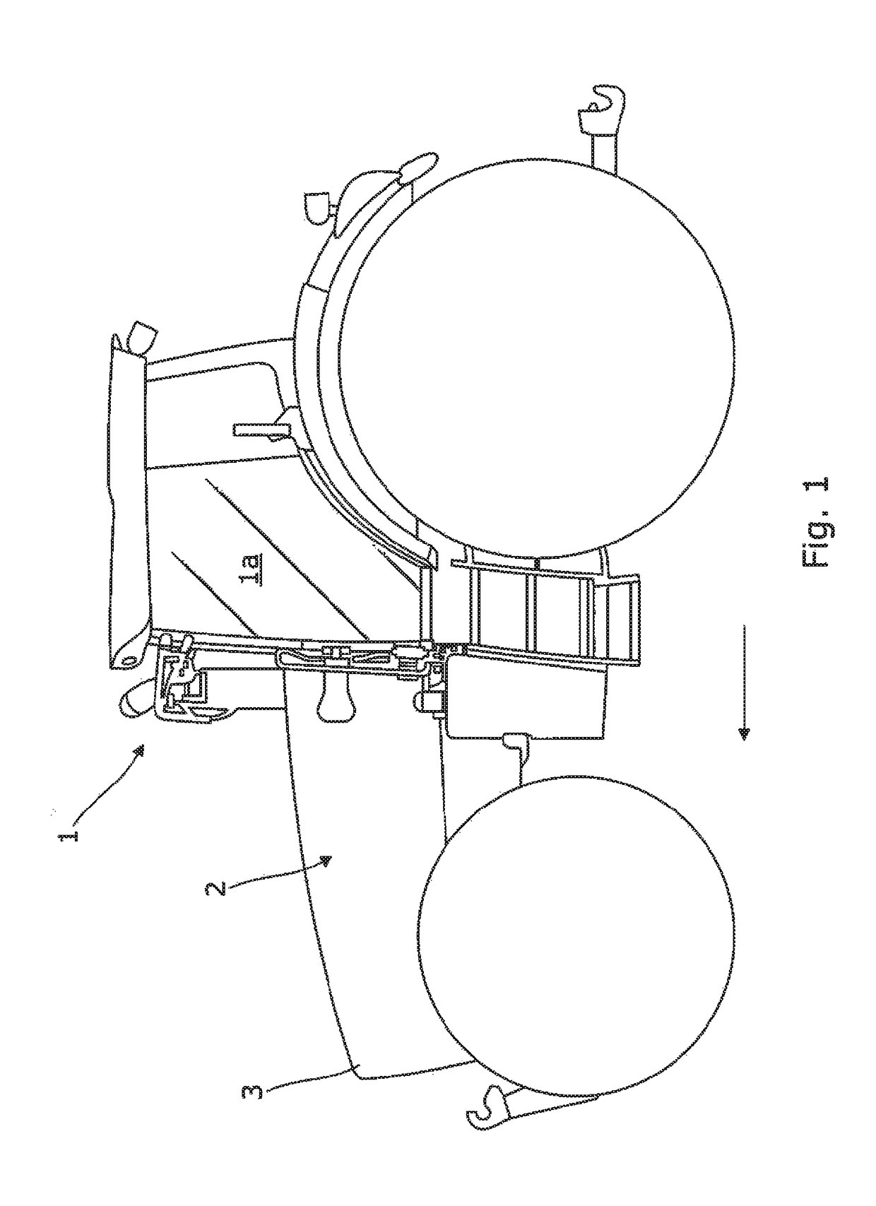
[0027]FIG. 1 is a side view of an agricultural tractor 1 having a front bonnet 2 which houses an engine and a cooling arrangement (not seen) in accordance with the invention. The bonnet 2 extends from a driver's cab la to the front of the tractor. A grill or mesh 3 is positioned at the front of the bonnet through which air passes and enters the cooling arrangement shown in FIGS. 2, 3 and 4. The arrow indicates the forward direction of travel.

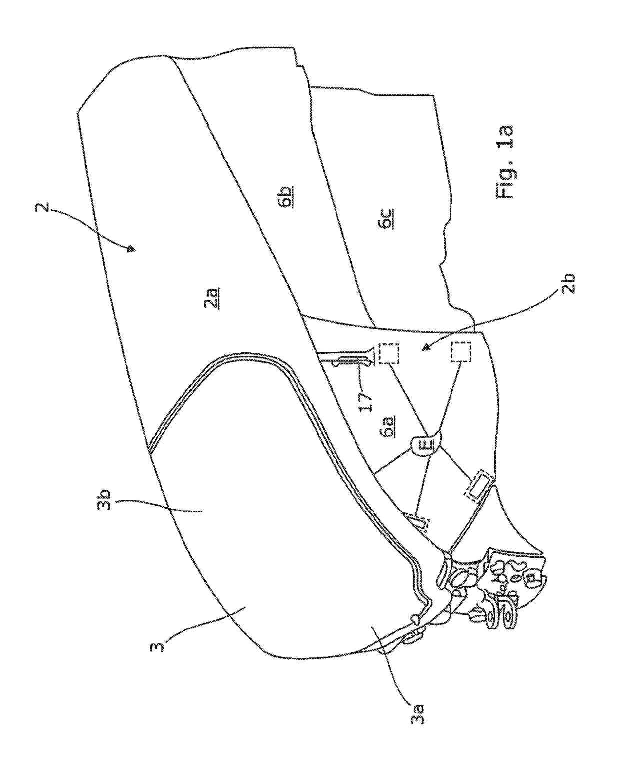
[0028]FIG. 1a is a perspective view of the bonnet of FIG. 1. The bonnet 2 comprises a hood 2a and two opposing side parts 2b. When the bonnet 2 is closed as shown in FIGS. 1 and 1a, the hood 2a has a fairly flat upper surface which extends in a generally horizontal manner from the cab. Towards the front of the vehicle, the upper surface of the hood 2a starts to slope downwards and has an almost vertical front part at the front of the tractor. The hood 2a has an overhang which extends a small vertical distance along each of the two long opposing ...


PUM


Abstract

A vehicle engine cooling arrangement including a fan, a radiator and a mounting plate. The plate provides a fan mounting surface and a radiator mounting surface so that the fan and radiator are in a spaced arrangement. The plate extends from under the fan at the front of the vehicle to under the radiator downstream of the fan and guides air from the fan to the radiator.

Description

BACKGROUND OF THE INVENTION[0001]Field of Invention[0002]This invention relates to a vehicle cooling system. More specifically, this invention relates to an air cooling arrangement on an agricultural vehicle.[0003]Description of Related Art[0004]Agricultural vehicles, such as agricultural tractors require a number of radiators in order to cool working media, such as a water cooler for the engine, a transmission oil cooler, a hydraulic oil cooler, an intercooler and possibly a condenser for an air-conditioning system. It is common practice to arrange the radiators in series one after the other under a bonnet of the vehicle so that air from a fan positioned at the front of the vehicle drives air through the series of radiators. Radiators in this arrangement, however can result in creating a high resistance to air flow. To overcome the resistance, a larger fan may be required. The radiator arrangement may also interrupt the air flow resulting in overheating of the radiator or radiators...

Claims


Application Information

Patent Timeline
Patent Type & Authority Patents(United States)
IPC IPC(8): B60K11/00B60K11/04F01P5/06B62D25/10
CPCB60K11/04F01P5/06B60Y2200/221B60Y2306/05B62D25/10F01P2070/50
Inventor OPITZ, MARCOBARZEN, ALEXANDER
Owner AGCO INT GMBH
Why Eureka
Try Eureka