Engine cooling system and method for vehicle applying turbocharger

a technology for engine cooling and turbochargers, which is applied in the direction of machines/engines, mechanical devices, lubrication temperature control, etc., can solve the problems of generating noise and reducing durability, and achieve the effects of reducing durability, preventing heat damage of turbochargers, and reducing durability

Active Publication Date: 2020-04-16
HYUNDAI MOTOR CO LTD +1
View PDF0 Cites 2 Cited by
  • Summary
  • Abstract
  • Description
  • Claims
  • Application Information

AI Technical Summary

Benefits of technology

[0031]It is possible to solve a problem in that the parts forming the turbocharger are exposed to a high temperature for a long time to reduce the durability because the turbocharger is cooled even if the engine is started-off immediately after the high load operation. The bearing part of the turbocharger increases in temperature due to an increase in RPM upon the high load operation, and when the engine is operated, coolant is supplied to be cooled to an appropriate temperature, but when the engine is started-off immediately after the high load operation, the cooling is not performed in a state where the temperature has increased to occur the heat damage, reducing the durability. However, when the coolant circulates to perform the cooling

Problems solved by technology

The circulation of the coolant is stopped with the start-off of the engine, such that when residual heat remains in some components of the engine compartment, the residual heat can cause heat damage, reducing durability.
Furthermore, there is

Method used


Image

  • Engine cooling system and method for vehicle applying turbocharger
  • Engine cooling system and method for vehicle applying turbocharger
  • Engine cooling system and method for vehicle applying turbocharger

Examples


Embodiment Construction

[0045]Reference will now be made in detail to various embodiments of the present invention(s), examples of which are illustrated in the accompanying drawings and described below. While the present invention(s) will be described in conjunction with exemplary embodiments of the present invention, it will be understood that the present description is not intended to limit the present invention(s) to those exemplary embodiments. On the other hand, the present invention(s) is / are intended to cover not only the exemplary embodiments of the present invention, but also various alternatives, modifications, equivalents and other embodiments, which may be included within the spirit and scope of the present invention as defined by the appended claims.

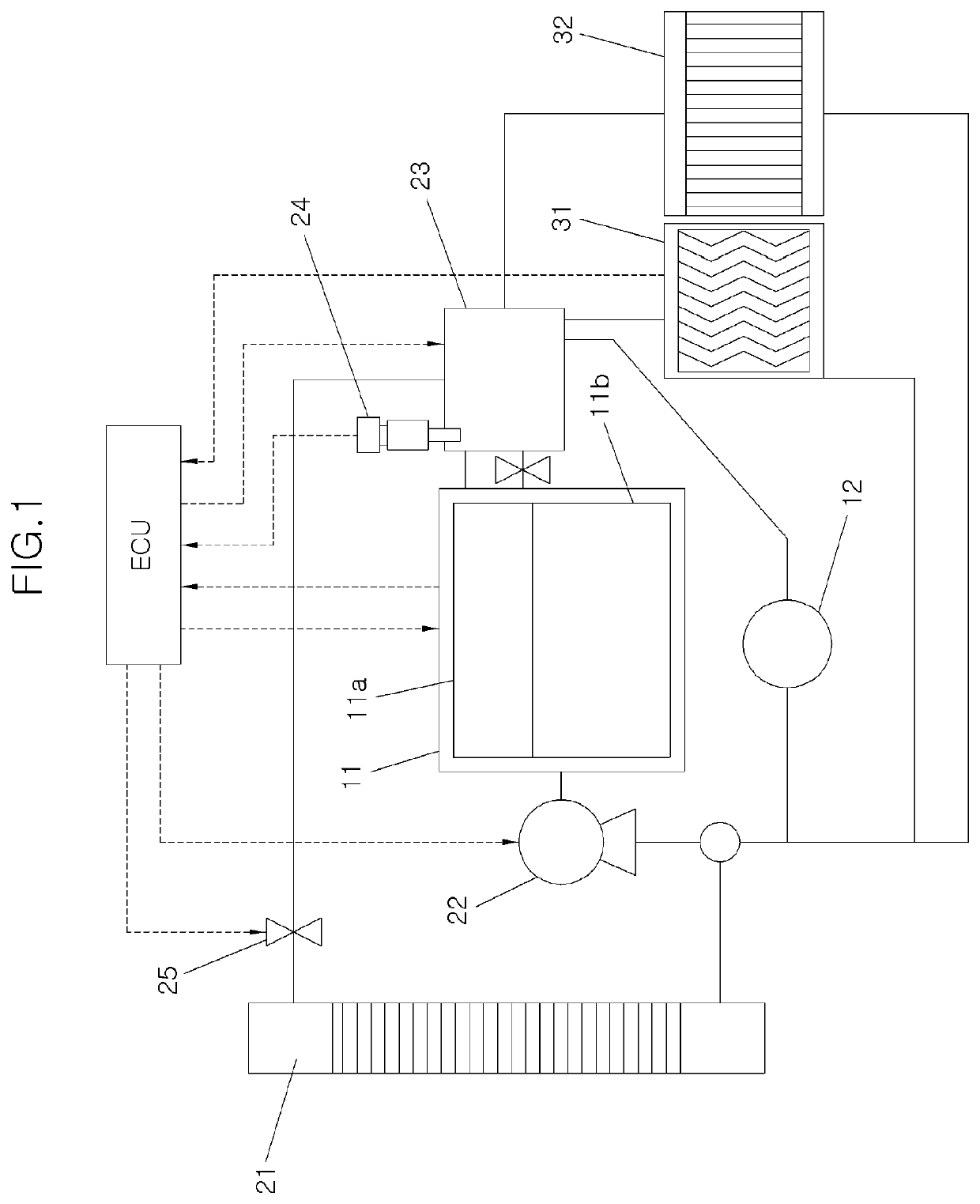
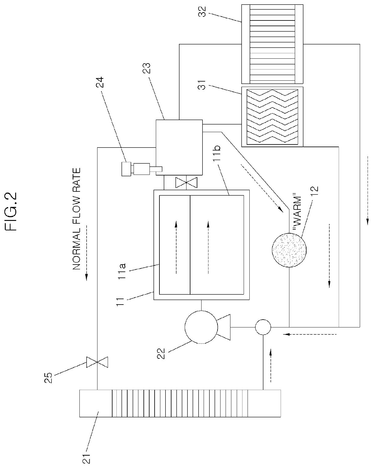
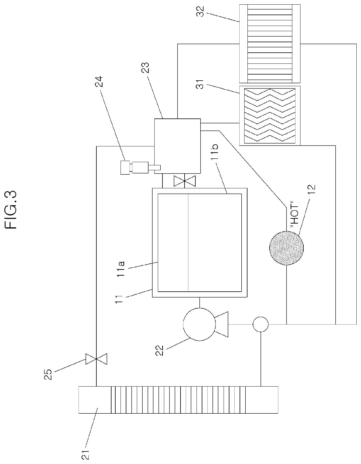
[0046]Hereinafter, an engine cooling system and method for a vehicle applying a turbocharger according to an exemplary embodiment of the present invention will be described in detail with reference to the accompanying drawings.

[0047]FIG. 1 is a dia...


PUM


Abstract

A method for cooling the engine for the vehicle applying the turbocharger may include comparing an average fuel consumption amount that determines, by a control unit, for controlling the operation of the engine and the circulation of the coolant, whether an average fuel consumption amount consumed in the engine immediately before the start-off of the engine is greater than a predetermined after-start-up cooling entrance average fuel consumption amount when the vehicle is started-off after a high load operation, and maximally cooling that controls, by the control unit, so that the coolant cooled in a radiator is circulated into the engine and the turbocharger by maximally opening a thermostat for controlling, and operating a water pump, when the average fuel consumption amount consumed in the engine immediately before a start-off of the engine is greater than the predetermined after-start-up cooling entrance average fuel consumption amount in the comparing the average fuel consumption amount.

Description

CROSS-REFERENCE TO RELATED APPLICATION[0001]The present application claims priority to Korean Patent Application No. 10-2018-0123319, filed on Oct. 16, 2018, the entire contents of which is incorporated herein for all purposes by this reference.BACKGROUND OF THE DISCLOSUREField of the Disclosure[0002]The present invention relates to an engine cooling system and method for a vehicle applying a turbocharger, which cool the turbocharger and an engine mounted with the turbocharger that are overheated upon engine-off immediately after a high load operation in the engine for the vehicle mounted with the turbocharger.Description of Related Art[0003]An engine is provided with a cooling system for cooling the heat generated by an operation of the engine.[0004]Generally, a cooling circuit is configured so that coolant circulates the engine and a radiator, and circulates the coolant to cool the heated engine.[0005]Furthermore, the coolant is also supplied to a turbocharger for operating with t...

Claims


Application Information

Patent Timeline
IPC IPC(8): F01P7/16
CPCF01P2023/08F01P7/16F01P3/20F01P3/02F01P3/12F01P5/10F01P7/165F01P7/162F01M5/005F02B39/005F01P2050/22F01P7/167F01P2060/12F01P5/12Y02T10/12F01P7/14F01P2007/146F01P2037/02F01P2025/40
Inventor LEE, SU-HOCHOI, EUI-CHULPARK, JUN-SIK
Owner HYUNDAI MOTOR CO LTD
Why Eureka
Try Eureka