Thermal management system for vehicle
a technology for managing systems and vehicles, applied in the direction of machines/engines, battery/fuel cell control arrangements, transportation and packaging, etc., can solve the problems of reducing the heat exchange performance of the heat-absorption heat exchanger, degrading and becoming useless, so as to improve the air-heating performance of the vehicle interior
- Summary
- Abstract
- Description
- Claims
- Application Information
AI Technical Summary
Benefits of technology
Problems solved by technology
Method used
Image

Examples
first embodiment
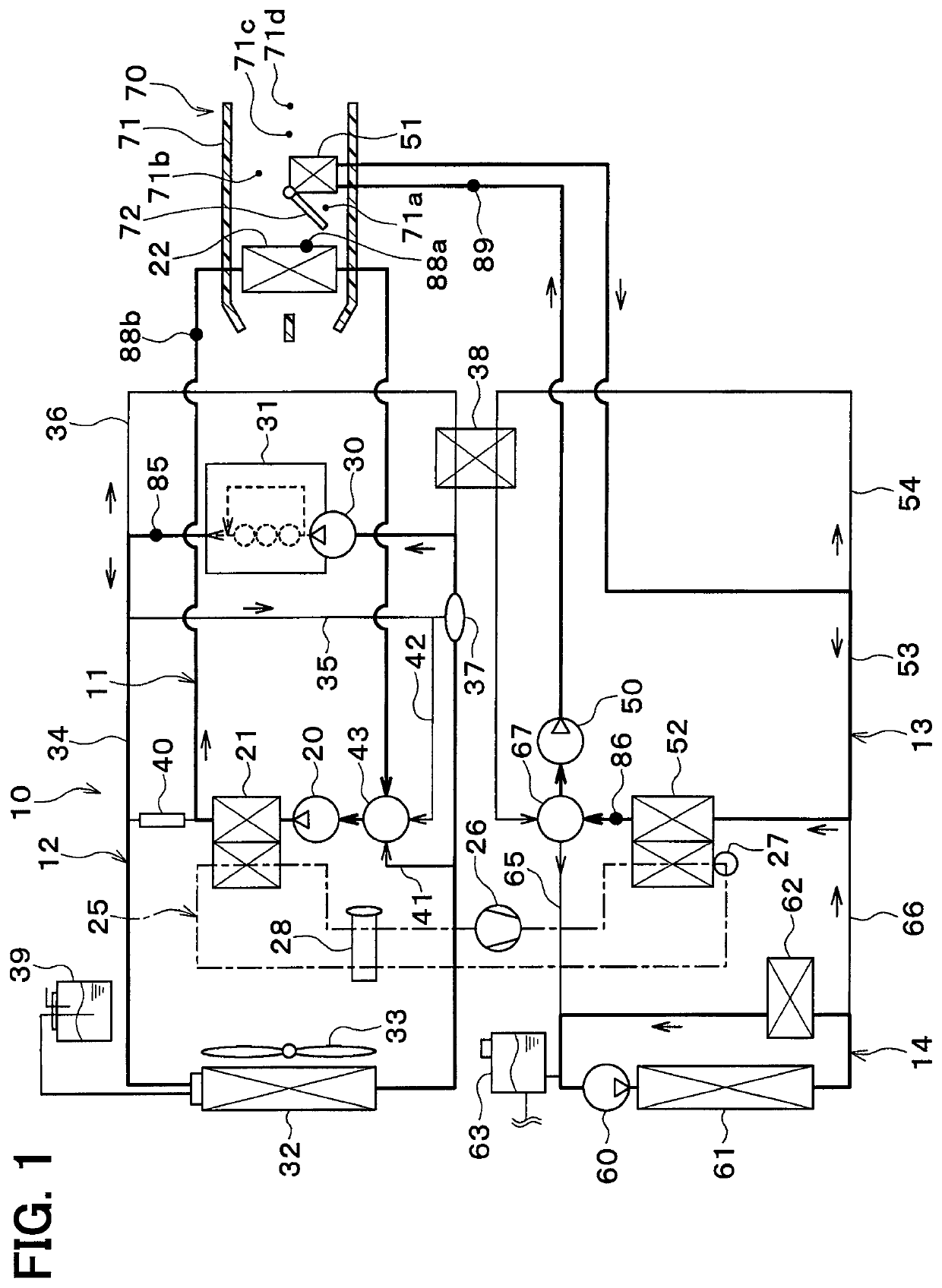
[0033]A vehicle thermal management system 10 shown in FIG. 1 is used to adjust various devices mounted on a vehicle or an interior of the vehicle to an appropriate temperature. In this embodiment, the vehicle thermal management system 10 is applied to a hybrid vehicle that can obtain a vehicle-travel driving force from both an engine (internal combustion engine) and a traveling electric motor.
[0034]The hybrid vehicle in this embodiment is configured as a plug-in hybrid vehicle that can charge the battery (vehicle-mounted battery) mounted on the vehicle, with power supplied from an external power source (commercial power source) during stopping of the vehicle. For example, a lithium ion battery can be used as the battery.
[0035]The driving force output from the engine is used not only to cause the vehicle to travel, but also to operate a power generator. The power generated by the power generator and the power supplied from an external power source can be stored in the battery. The po...
second embodiment
[0283]In the above-mentioned embodiment, the coolant in the engine cooling circuit 12 and the coolant in the condenser circuit 13 have their heat exchanged therebetween via the coolant-coolant heat exchanger 38. In this embodiment, as shown in FIG. 10, the engine cooling circuit 12 and the condenser circuit 13 can be directly connected with each other.
[0284]In this embodiment, a heater-core flow path 100 is connected to the circulation flow path 34 in the engine cooling circuit 12. The heater-core flow path 100 is a coolant flow path in which the heater core 51 is disposed.
[0285]One end of the heater-core flow path 100 is connected to a part on the coolant outlet side of the engine 31 in the circulation flow path 34. Further, the one end of the heater-core flow path 100 is connected to a part on the coolant suction side of the engine pump 30 in the circulation flow path 34.
[0286]In this embodiment, the heater pump 50, the condenser 52, and the heater-side radiator 61 are arranged in...
third embodiment
[0323]In the above-mentioned embodiments, the condenser 52 that exchanges heat between the high-pressure side refrigerant and the coolant is provided as a condenser for condensing the high-pressure side refrigerant in the refrigeration cycle 25. However, in this embodiment, as shown in FIG. 15, an interior condenser (air heating device) 110 and an exterior condenser 111 are provided as the condenser for the refrigeration cycle 25.
[0324]The interior condenser 110 and the exterior condenser 111 are arranged in series so as to cause the refrigerant to flow in this order in the refrigeration cycle 25.
[0325]The interior condenser 110 is an interior heat exchanger that heats the air to be blown into the vehicle interior while condensing the high-pressure side refrigerant by exchanging heat between the high-pressure side refrigerant discharged from the compressor 26 and the air to be blown into the vehicle interior. The interior condenser 110 is disposed on the downstream side in the air f...
PUM
 Abstract
Description
Claims
Application Information
 - R&D Engineer
- R&D Manager
- IP Professional
- Industry Leading Data Capabilities
- Powerful AI technology
- Patent DNA Extraction
Browse by: Latest US Patents, China's latest patents, Technical Efficacy Thesaurus, Application Domain, Technology Topic.
© 2024 PatSnap. All rights reserved.Legal|Privacy policy|Modern Slavery Act Transparency Statement|Sitemap