Efficient hybrid engine cooling system and engine cooling method

An engine cooling and high-efficiency technology, applied in the direction of engine cooling, engine components, engine lubrication, etc., can solve the problems of poor turbocharged cooling effect, large electronic water pump workload, and small cooling demand, etc. Little change in layout, maintenance of reliability, effect of short circulation loop

Active Publication Date: 2020-11-03
GUANGXI YUCHAI MASCH CO LTD
View PDF7 Cites 3 Cited by
  • Summary
  • Abstract
  • Description
  • Claims
  • Application Information

AI Technical Summary

Problems solved by technology

[0006] In the above-mentioned prior art, electronic water pumps are used, which can cool the turbocharger after the engine stops, but there are still deficiencies: after the engine stops, the cooling passages of the main water pump and the oil cooler are not cut off, and the electronic water pump is still working. Water is supplied to the thermostat, radiator and oil cooler cooling water passage in the main cooling water passage of the engine, which greatly diverts the coolant flow through the turbocharger, and the oil cooler is far away from the combustion chamber and exhaust pipe, and its cooling The demand is small and there is no need to cool down after shutdown
This results in a large workload for the electronic water pump, and the cooling effect of the turbocharger is not good.

Method used


Image

  • Efficient hybrid engine cooling system and engine cooling method
  • Efficient hybrid engine cooling system and engine cooling method
  • Efficient hybrid engine cooling system and engine cooling method

Examples


Embodiment 1

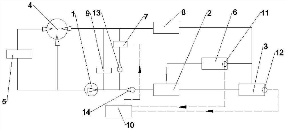
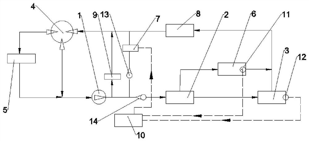
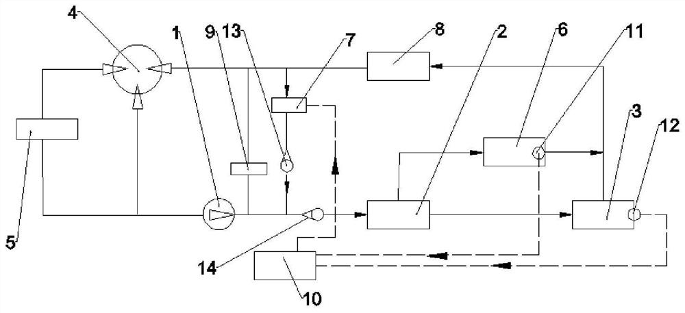
[0041] Such as figure 1 Shown: a high-efficiency hybrid engine cooling system, including the main mechanical water pump 1, the cylinder head water jacket 2, the cylinder water jacket 3, the EGR cooler 8, the thermostat 4 and the radiator 5, which are sequentially connected from end to end to form a water cycle, It also includes an oil cooler 9 whose two ends are respectively connected to the water outlet of the main mechanical water pump 1 and the water outlet of the EGR cooler 8, and whose two ends are respectively connected to the cylinder head water jacket 2 and the water inlet of the EGR cooler 8. The supercharger water jacket 6 is characterized in that: a second one-way valve 13 and an electronic water pump 7 are sequentially arranged in series between the water inlet end of the cylinder head water jacket 2 and the water outlet end of the EGR cooler 8, so that The main waterway between the oil cooler 9 and the second one-way valve 13 is provided with a first one-way valve...

Embodiment 2

[0045] Such as figure 1 As shown, a high-efficiency hybrid engine cooling system includes a main mechanical water pump 1, a cylinder head water jacket 2, a cylinder block water jacket 3, an EGR cooler 8, a thermostat 4 and a radiator 5, which are sequentially connected from end to end to form a water cycle. The present invention adopts a top-down cooling method, that is, cooling water flows from the water jacket 2 of the cylinder head to the water jacket 3 of the cylinder body, and the cooling liquid first flows through the cylinder head and then to the machine body, so that the cooling effect is good.

[0046] This embodiment also includes an oil cooler 9 whose two ends are respectively connected to the water outlet of the main mechanical water pump 1 and the water outlet of the EGR cooler 8, and the two ends are respectively connected to the cylinder head water jacket 2 and the EGR cooler 8. The supercharger water jacket 6 at the water inlet, the EGR cooler 8 is connected in...

Embodiment 3

[0053] This embodiment is an engine cooling method, which adopts a high-efficiency hybrid engine cooling system in the above-mentioned embodiment 2, including the following steps:

[0054] S1. The rotational speed sensor 12 detects the rotational speed of the engine, and the ECU 10 judges the working state of the engine; when the engine is in the running state, the main mechanical water pump 1 is controlled to work; when the engine changes from the running state to the stopped running state, enter step S2;

[0055] S2. Set the water temperature threshold T1>T2>T3, the water temperature sensor 11 detects the water temperature at a time interval Δt, if the current water temperature T is greater than T1 and the water temperature T rises, enter step S201; if the current water temperature T is greater than T1 and the water temperature T decreases , enter step S202; if the current water temperature T is less than T1 and the water temperature T rises, enter step S203; if the current w...


PUM


Abstract

The invention relates to the technical field of engines, in particular to an efficient hybrid engine cooling system and an engine cooling method. The efficient hybrid engine cooling system comprises amain mechanical water pump, a cylinder cover water jacket, a cylinder body water jacket, an EGR cooler, a temperature regulator and a radiator which are sequentially communicated end to end to form water circulation. A second one-way valve and an electronic water pump are sequentially connected between the water inlet end of the cylinder cover water jacket and the water outlet end of the EGR cooler in series, a first one-way valve is arranged on a main water way between an engine oil cooler and the second one-way valve, and the circulation direction of the first one-way valve is consistent with that of the main water way. The circulation direction of the second one-way valve is set to be the direction from the electronic water pump to the second one-way valve. According to the system andthe method, a circulation loop is the shortest after an engine is shut down, the resistance is low, the heat dissipation efficiency of a turbocharger is improved, and the operation reliability of theengine is maintained.

Description

technical field [0001] The invention relates to the technical field of engines, in particular to a high-efficiency hybrid engine cooling system and an engine cooling method. Background technique [0002] The cooling system is an important part of the engine. During the operation of the engine, the parts in contact with high-temperature gas or exhaust are strongly heated, and the cooling system is required to dissipate the excessive heat on these parts, otherwise various adverse consequences will occur, such as: deterioration of lubricating oil, damage of normal oil film; The heated parts expand and destroy the normal clearance of the kinematic pair; the thermodynamic performance of the parts decreases or even fails. In addition, it should not be cooled too much, otherwise it will cause poor combustion, increase emissions, and reduce fuel economy; the viscosity of the engine oil will increase, the friction loss of the moving pair will increase, and the engine will work rough...

Claims


Application Information

Patent Timeline
Patent Type & Authority Applications(China)
IPC IPC(8): F01P3/00F01P3/18F01P3/20F01P5/12F01P7/16F01M5/00F02M26/22
CPCF01P3/00F01P3/18F01P3/20F01P5/12F01P7/164F01P7/167F01M5/002F02M26/22F01P2005/105F01P2005/125F01P2007/143Y02T10/12
Inventor 冉景旭梁德浦毛龙归刘益军覃星念
Owner GUANGXI YUCHAI MASCH CO LTD
Why Eureka
Try Eureka