Camera with heating element

a technology of heating element and camera, which is applied in the field of cameras with heating elements, can solve the problems of direct contact with the surrounding environment, adverse effects on camera functions, and exposure of cameras, and achieve the effects of avoiding frost and condensation, being durable and reliably used outdoors, and resisting frost and condensation

Active Publication Date: 2017-04-11
MEKRA LANG GMBH & CO KG
View PDF18 Cites 4 Cited by
  • Summary
  • Abstract
  • Description
  • Claims
  • Application Information

AI Technical Summary

Benefits of technology

[0011]It is an object of the present disclosure to provide a camera that can be permanently and reliably used outdoors, resist frost and condensations caused by temperature differences and, thus, operate fault-free, while ensuring cost-effective and simple production.
[0013]The component to be preferably heated up is the component that is in direct contact with the environment and, therefore, exposed to weather conditions. If the camera is, for example, provided with a cover glass, it is primarily the cover glass, which cover glass may also be considered an optical element, that has to be heated up in order to eliminate frost or condensation on said cover glass. In cameras without cover glass, it primarily is the optical element which is in direct contact to the environment that has to be heated up, for example, the lens. Usually, the camera is sealed against entry of moisture.
[0018]Arranging the at least one heating element directly on the circuit board of a group of circuit boards, which is already provided in the camera and has an active circuit for carrying out direct camera functions, allows for efficient and cost-effective production, as no modifications have to be made with regard to the camera housing. The heat transfer to the components to be preferably heated up is increased. Preferably, at least one heating element is applied to the circuit board by means of a resistor layer. The at least one heating element is preferably connected with a power source and, for example, a control device, which supply control signals and electrical energy, which is then converted into heat, to the at least one heating element. Preferably, the electrical connection to the power source and / or to the control device is also printed on the circuit board.
[0023]In a preferred embodiment, at least one heat conducting element is directly arranged between a circuit board of the group of circuit boards and the housing and / or directly between the at least one heating element and the housing. The heat conducting element is preferably made of a material having good thermal conductivity, like silver, copper, and / or aluminum. At least one heat conducting element is preferably a heat conductive adhesive, a thermal paste and / or a heat conducting pad. The heat conducing element may, for example, be a single-component epoxy resin adhesive made of solvent-free reaction resin, or an adhesive with fillers to which solid components like quartz powder, chalk, metal powder, soot etc. are added in order to improve thermal conductivity. In one embodiment, at least one circuit board of the group of circuit boards is fixed to the housing by means of at least one heat conducting element. In a preferred embodiment, the heat conducing element fully extends over at least one heating element that is attached to a circuit board of the group of circuit boards, so that the surface for effective heat transfer is maximized.
[0026]Moreover, in preferred embodiments, a cover glass is provided which, in such embodiments, is considered to be the optical element to be heated up. The cover glass may seal the housing on the object-side in an airtight and / or watertight manner. The cover glass is preferably connected to the housing and is also heated up by the housing, which is heated by the at least one heating element, so that frost and / or condensation forming on the cover glass may be avoided or eliminated.

Problems solved by technology

Thus, the cameras are exposed to weather conditions prevailing at the location of the vehicle.
In particular at cold temperatures, for example in winter, the cover glass and / or the camera lens may be covered with frost and / or condensation and, thus, the camera functions may be adversely affected.
Here, particularly the optical elements of the camera that are located at the outside of the housing and, thus, in direct contact with the surrounding environment may be covered with frost and / or condensation.
Also the function and image quality of cameras arranged on the vehicle, such as, for example, rear-view cameras, may be affected by frost and / or condensation.
Especially after repeated formation of condensation and / or frost, these components may eventually suffer damage.
This is often relatively complex with regard to installation of the heating elements within the camera housing during the manufacturing process.
Moreover, a camera housing usually made of metal has a better thermal conductivity compared to the optical elements usually made of plastics or glass, and thus, when providing the heating elements within the housing, the larger part of the thermal energy introduced by the heating elements is received by the camera housing or possibly even lead away from the optical elements, so that only a minor part of this thermal energy may cause heating of the optical elements.

Method used


Image

  • Camera with heating element
  • Camera with heating element
  • Camera with heating element

Examples


Embodiment Construction

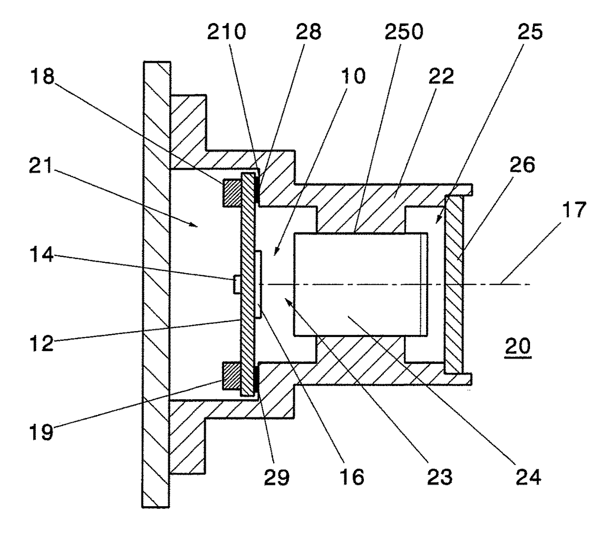
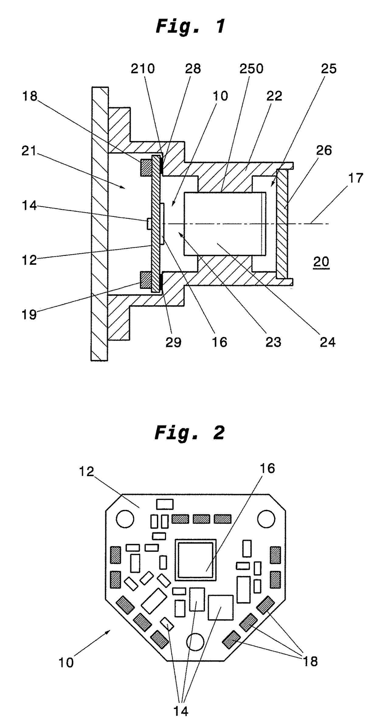
[0040]FIG. 1 shows a first embodiment of a camera 20 according to the present disclosure. The camera 20 is provided with a housing 22 including cylindrical inner portions 21, 23, 25 having different diameters. A group of circuit boards having a single circuit board 10, which is arranged in the inner portion 21, and an optical element 24, which is arranged in the inner portion 25 whose diameter is smaller than the diameter of inner portion 21, are arranged within the housing 22. The inner portion 25 is stepped with regard to the inner portion 23 and has a housing inner flange surface 210. The circuit board 10 is attached to a housing inner flange surface 210. The optical element 24 is, for example, a lens with lens system and is screwed into the housing 22 at the inner portion 25, whose diameter is smaller than the diameter of inner portion 23, by means of a thread 250. On the object-side, the housing 22 is sealed in an airtight and / or watertight manner by a further optical element i...


PUM


Abstract

A camera for use on vehicles, in particular commercial vehicles. The camera has a housing, at least one optical element disposed within the housing, a group of circuit boards disposed within the housing and including at least one circuit board. The group of circuit boards has at least one active circuit for executing a direct camera function. The camera further comprises at least one heating element adapted for heating the group of circuit boards, the optical elements, and / or the housing, wherein the at least one heating element is directly attached to one of the circuit boards of the group of circuit boards.

Description

BACKGROUND OF THE INVENTION[0001]1. Field of the Invention[0002]The present disclosure relates to a camera comprising at least one heating element, in particular to a camera comprising at least one heating element for use on a vehicle, for example, on a commercial vehicle.[0003]2. Description of the Related Art[0004]In recent times it has been increasingly considered to use, besides conventional mirrors as means for indirect vision, in addition to or as replacement for these mirrors, camera systems or image capturing systems as means for indirect vision, wherein an image capturing unit, e.g. a camera, continuously detects a recorded image, and wherein the (video) data captured by the image capturing unit are submitted, for example by means of a calculation unit and possibly after further processing, to a display unit within the driver's cab, which display unit permanently, always visible, and in real time displays the respective captured field of vision and possibly further informat...

Claims


Application Information

Patent Timeline
Patent Type & Authority Patents(United States)
IPC IPC(8): H04N5/225G03B17/55
CPCG03B17/55H04N5/2251H04N5/2252H04N5/2254H04N23/52H04N23/51H04N23/55
Inventor LANG, WERNERGEISSENDORFER, PETERKUNZ, MANUELWITZKE, MICHAELCENTMAYER, STEFANHORNUNG, MICHAEL
Owner MEKRA LANG GMBH & CO KG
Why Eureka
Try Eureka