Liquid supply unit
a technology of liquid supply and unit, applied in printing, other printing apparatus, etc., can solve the problems of bridging part of the apparatus or no
- Summary
- Abstract
- Description
- Claims
- Application Information
AI Technical Summary
Benefits of technology
Problems solved by technology
Method used
Image
Examples
first embodiment
A. First Embodiment
A-1. Overall Configuration of Liquid Jet System
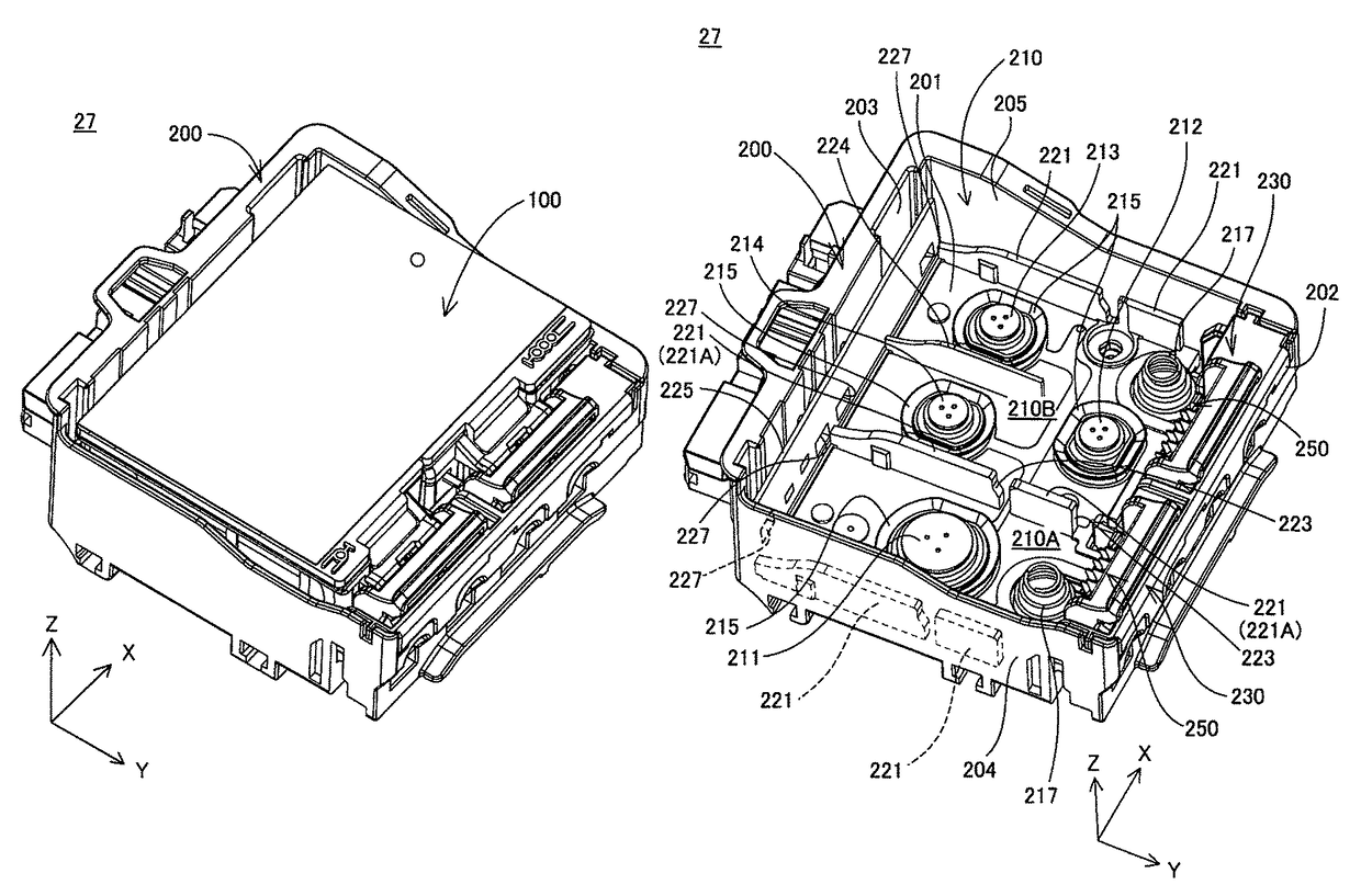
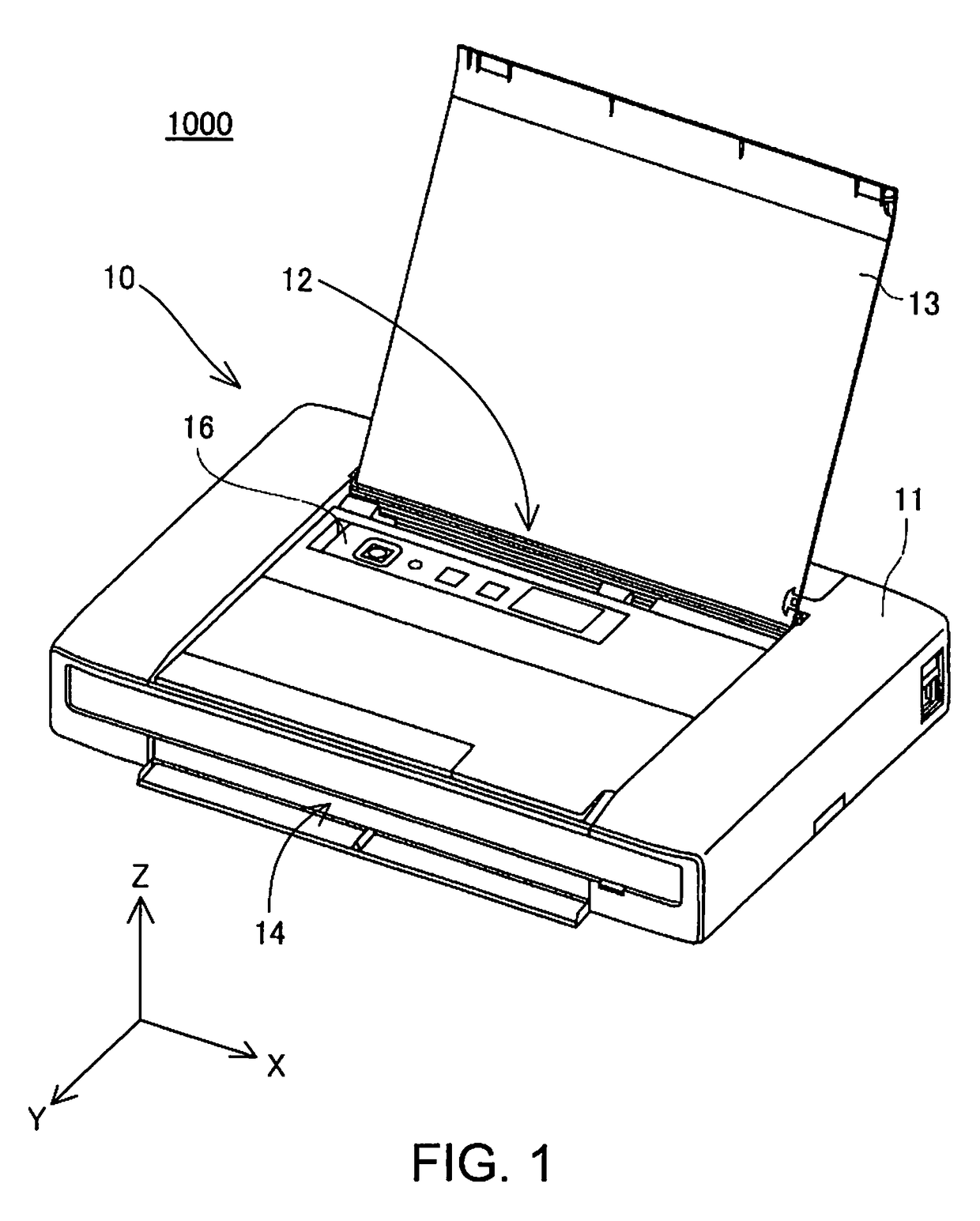
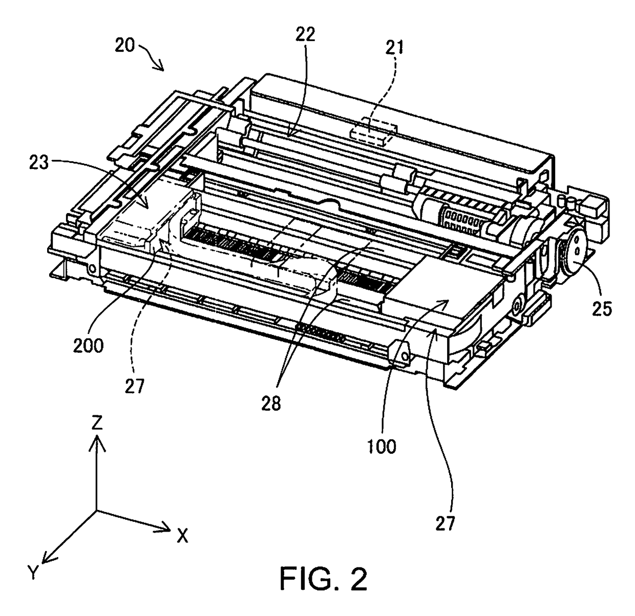
[0070]FIG. 1 is a schematic perspective view showing an external configuration of a liquid jet system 1000 serving as a first embodiment of the invention. The liquid jet system 1000 is provided with a printing apparatus 10 serving as a liquid jet apparatus, and a liquid supply unit (liquid supply container) which will be discussed later. In FIG. 1, arrows X, Y and Z indicating three directions intersecting each other orthogonally are illustrated. The arrow X indicates a right-left direction that is parallel to a lateral direction (width direction) of the printing apparatus 10, and indicates the direction from the left side to the right side when a user directly faces the printing apparatus 10. In this embodiment, the direction of the arrow X (+X direction) is parallel to a main scanning direction of a cartridge mounting part 27 in the printing apparatus 10 (discussed later). The arrow Y indicates a direction parallel ...
second embodiment
B. Second Embodiment
[0130]FIG. 16 is a bottom view of a liquid supply unit 100a serving as a second embodiment. FIGS. 17A to 17D are diagrams for describing the liquid supply unit 100a. FIG. 17A is a cross-sectional view along F16A-F16A in FIG. 16. FIG. 17B is a cross-sectional view along F16B-F16B in FIG. 16. FIG. 17C is a cross-sectional view along F16C-F16C in FIG. 16. FIG. 17D is a cross-sectional view along F16D-F16D in FIG. 16. The liquid supply unit 100a of the second embodiment differs from the liquid supply unit 100 of the first embodiment in that the liquid supply unit 100a is newly provided with a bridging part 189. Since the liquid supply unit 100a and the liquid supply unit 100 are similar in terms of the remaining configuration, the same reference signs will be given to the configuration that is similar and description thereof will be omitted. Also, the liquid supply unit 100a of the second embodiment is detachably mounted in the cartridge mounting part 27 (FIG. 4), si...
third embodiment
C. Third Embodiment
[0132]FIG. 18 is a bottom view of a liquid supply unit 100b serving as a third embodiment. FIGS. 19A to 19D are diagrams for describing the liquid supply unit 100b. FIG. 19A is a cross-sectional view along F18A-F18A in FIG. 18. FIG. 19B is a cross-sectional view along F18B-F18B in FIG. 18. FIG. 19C is a cross-sectional view along F18C-F18C in FIG. 18. FIG. 19D is a cross-sectional view along F18D-F18D in FIG. 18. The liquid supply unit 100b of the third embodiment differs from the liquid supply unit 100a of the second embodiment in that the liquid communication part 140b is provided with a bridging part 189b. Since the liquid supply unit 100b and the liquid supply unit 100a are similar in terms of the remaining configuration, the same reference signs will be given to the configuration that is similar and description thereof will be omitted. Also, the liquid supply unit 100b of the third embodiment is detachably mounted in the cartridge mounting part 27 (FIG. 4), s...
PUM
 Abstract
Description
Claims
Application Information
 - R&D
- Intellectual Property
- Life Sciences
- Materials
- Tech Scout
- Unparalleled Data Quality
- Higher Quality Content
- 60% Fewer Hallucinations
Browse by: Latest US Patents, China's latest patents, Technical Efficacy Thesaurus, Application Domain, Technology Topic, Popular Technical Reports.
© 2025 PatSnap. All rights reserved.Legal|Privacy policy|Modern Slavery Act Transparency Statement|Sitemap|About US| Contact US: help@patsnap.com


