Unlock instant, AI-driven research and patent intelligence for your innovation.

Shock wave modification in percussion drilling apparatus and method

a percussion drilling and shock wave technology, applied in the direction of drilling rods, drilling pipes, percussion drilling, etc., can solve the problems of not optimizing the existing percussion drilling system to reduce as far as possible energy loss, and achieve the effect of minimising any changes

Inactive Publication Date: 2017-05-02
SANDVIK INTELLECTUAL PROPERTY AB
View PDF15 Cites 0 Cited by
  • Summary
  • Abstract
  • Description
  • Claims
  • Application Information

AI Technical Summary

Benefits of technology

The present invention aims to modify the shock waves received at each threaded coupling in drill tools to minimize any detrimental changes to the shock wave shape profile that could impact the energy delivery to the rock. This is achieved through a shock wave modification sleeve that is mounted on an energy transmission adaptor. By configuring the sleeve with a free end suspended radially from the adaptor, the shock wave type can be converted and the amplitude characteristics significantly changed. The ratio of the sleeve to the hydraulically driven piston is selectively removed amplitude from an initial section and super positioned at a later section, resulting in optimal energy transmission efficiency. The sleeve is designed to maximize the use of the delivered energy at the drill bit, providing maximum energy transfer. The length section of the sleeve is aligned coaxially with the length section of the adaptor to minimize installation inconvenience. The sleeve wall thickness may be uniform or vary to change the characteristics of the transmitted shock wave. The invention provides an apparatus and method compatible for use with existing hydraulic hammering systems.

Problems solved by technology

This loss results from differences in the cross sectional area between the male and female threaded couplings involving reflections and impedance transmissions that generally change the shape of the shock wave as it propagates.
However, existing percussion drilling systems are not optimised to reduce as far as possible energy loses within the shock wave as it propagates along the entire length of the drill string whilst delivering an energy shock wave at the drill string tool having a shape characteristic is optimised for rock breakage.

Method used


Image

  • Shock wave modification in percussion drilling apparatus and method
  • Shock wave modification in percussion drilling apparatus and method
  • Shock wave modification in percussion drilling apparatus and method

Examples


Embodiment Construction

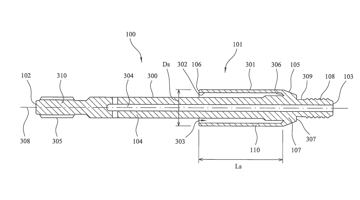
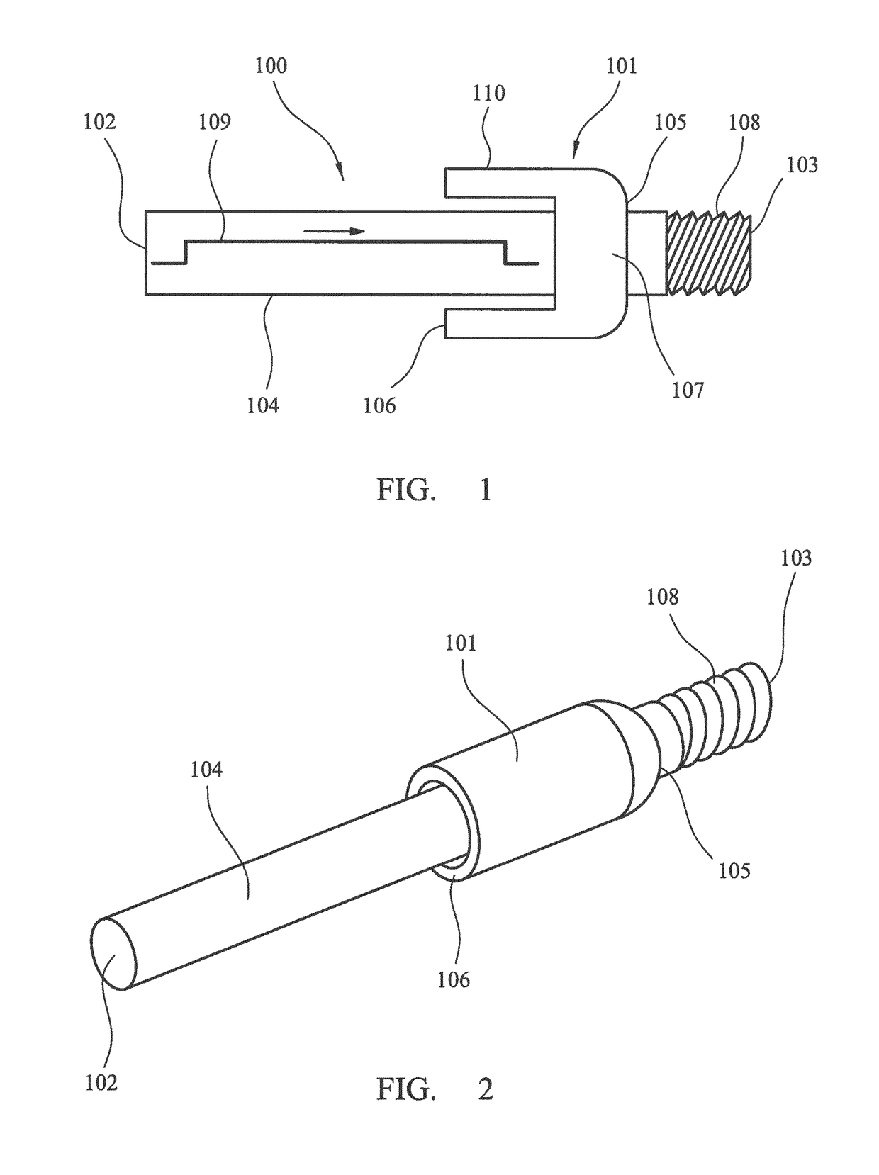
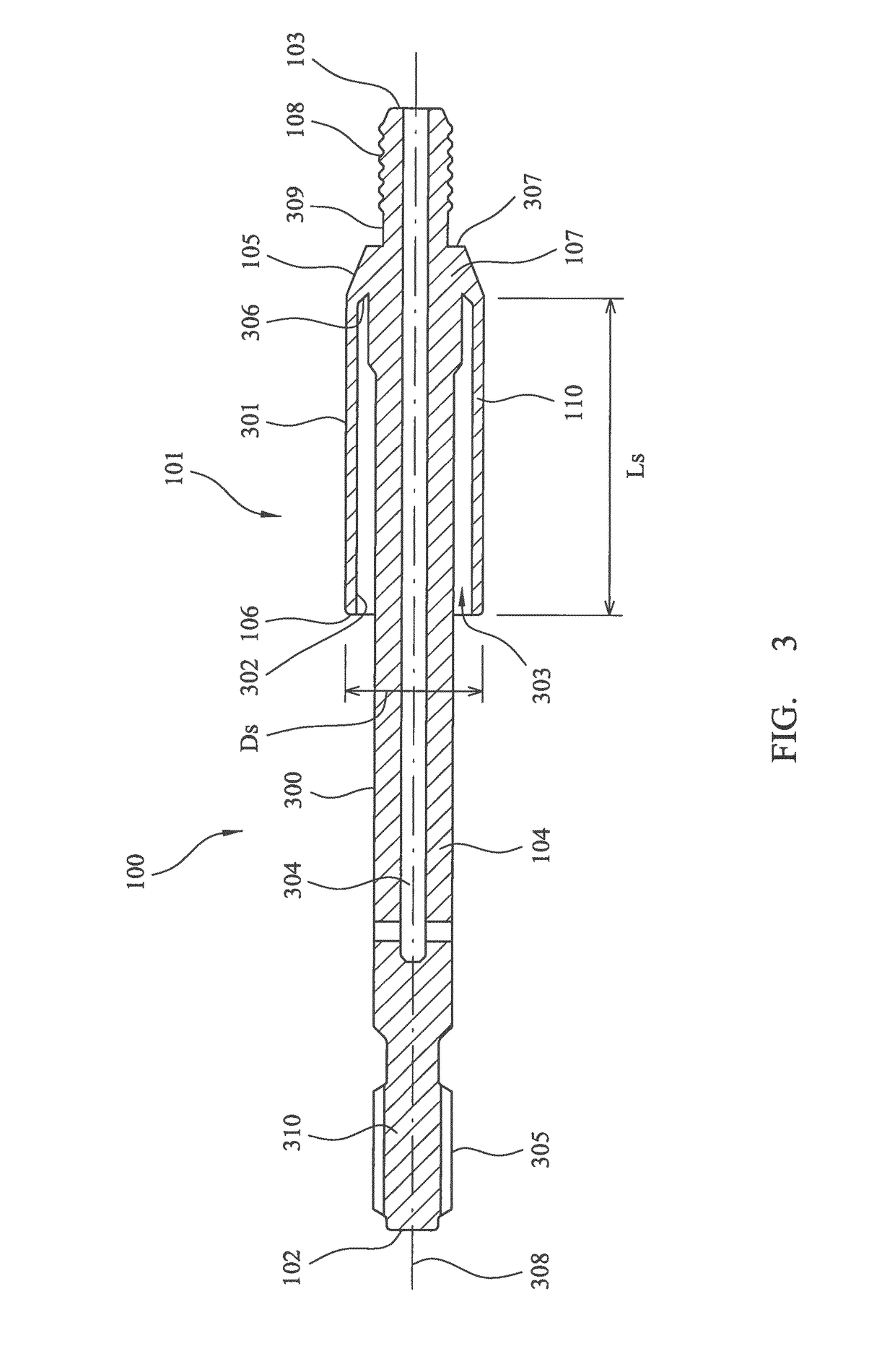
[0031]Referring to FIG. 1, an elongate energy transmission adaptor 100 comprises a main length section 104 having a rearward end 102 and a forward end 103. A shock wave modification sleeve 101 projects radially from the main length section 104 and extends axially along the region of section 104 axially between adaptor ends 102, 103. In particular, sleeve 101 comprises an attachment end 105 that is connected to a region of adaptor main length section 104 and an annular free end 106 that is suspended radially from and encircles adaptor main length section 104. Sleeve 101 comprises a main length section 110 extending axially between ends 105, 106. Attachment end 105 is formed as an annular radially extending wall 107 that projects from adaptor length section 104 at an axial region closer to forward end 103 than rearward end 102. To enable adaptor 100 to be coupled to a drill string, forward end 103 comprises a threaded end section 108 configured as a male spigot for coupling and housin...


PUM


Abstract

A percussion drilling apparatus is arranged to affect at least one characteristic of a shock wave produced in a drill string. The apparatus includes an elongate energy transmission adaptor having a shock wave modification sleeve configured with a free end and an attachment end projecting radially from an outer surface of the adaptor.

Description

RELATED APPLICATION DATA[0001]This application is a §371 National Stage Application of PCT International Application No. PCT / EP2014 / 068126 filed Aug. 27, 2014 claiming priority of EP Application No. 13183520.9, filed Sep. 9, 2013.FIELD OF INVENTION[0002]The present invention relates to percussion drilling apparatus and a method in which at least one characteristic of a shock wave produced in the drill string is modified to optimise drilling performance.BACKGROUND ART[0003]Percussion drilling is a well-established technique that breaks rock by hammering impacts transferred from the rock drill bit, mounted at one end of a drill string, to the rock at the bottom of the borehole. The energy needed to break the rock is generated by a hydraulically driven piston that contacts a shank adaptor positioned at the opposite end of the drill string to the drill tool. The piston strike on the adaptor creates a stress (or shock) wave that propagates through the drill string and ultimately to the b...

Claims


Application Information

Patent Timeline
Patent Type & Authority Patents(United States)
IPC IPC(8): E21B17/042E21B1/00E21B1/02
CPCE21B17/0426E21B1/00E21B1/02E21B1/24
Inventor JANSSON, TOMAS SHRINDESKAR, ANDREAS
Owner SANDVIK INTELLECTUAL PROPERTY AB