Yield monitoring system

a monitoring system and a technology of a monitoring plate, applied in the direction of mechanical equipment, transportation and packaging, valve types, etc., can solve the problems of insufficient, prone to slipping, and small impact plate that may not provide accurate measurement of flow, etc., and achieve the effect of accurate measuremen

Active Publication Date: 2017-05-09
OXBO INT CORP
View PDF9 Cites 4 Cited by
  • Summary
  • Abstract
  • Description
  • Claims
  • Application Information

AI Technical Summary

Benefits of technology

[0007]The present invention is directed to a yield monitoring system for a harvester. Grain harvesters and in particular corn harvesters for ear corn utilize combined harvesting and threshing to achieve a clean grain and in the case of ear corn harvesters, ears of corn. Such combines include a monitoring system to determine the yield from the harvest. Such information may be utilized in many ways for improved crop management practices. The yield monitoring system of the present invention is placed in a position within the flow of clean grain to deflect ears of corn and provide a measurement of the force from the flow and therefore determine a yield. An enlarged strike plate is utilized that deflects a large portion of the flow as compared to prior art systems. The larger strike plate includes a parallelogram type support assembly that provides even distribution of forces no matter where engaged by the strike plate and passes the force along to a load cell in an even manner to provide more accurate measurement to determine yield.
[0010]The yield monitoring system of the present invention provides for stable mounting over with spaced apart support points providing a larger base for the strike plate that ensures aligned and accurate engagement with a load cell sensor even if impact forces are due to striking an edges of a strike plate or are unevenly applied, as may occur with the small prior art direct mounting systems. The translational movement provides more accurate measurement and ensures a constant engagement angle with the load cell sensor. Moreover, the larger strike plate intercepts a larger percentage of the clean grain flow and provides more accurate measurement. The support assembly also provides for direct aligned engagement between the support bracket of the strike plate and the sensing tab of the load cell to overcome problems that may occur due to misalignment from prior art systems.

Problems solved by technology

Although such yield measurement systems may be satisfactory for many applications, there are problems.
The small impact plate may not provide an accurate measurement of the flow.
For certain types of crops in which the fruit or vegetables are relatively large, such as for example ear corn, potatoes, citrus and similar sized crops, such systems are more prone to error and may not provide satisfactory results.
However, depending on where the particular ears strike the impact plate, the force may not be accurately conveyed to and sensed by the load cell.
Moreover, the flow path in an ear corn or other harvester for relatively large crops is larger than for other types of grain harvesters and a relatively small impact plate may not intercept a sufficient percentage of the crop flow and may not therefore accurately reflect the actual flow.
Moreover, the direct mounting of the load cell to the impact plate results in inaccuracies should the ears of corn strike an edge of the plate or otherwise impact the plate at varied angles, which may not press the plate squarely against the load cell.

Method used


Image

  • Yield monitoring system
  • Yield monitoring system
  • Yield monitoring system

Examples


first embodiment

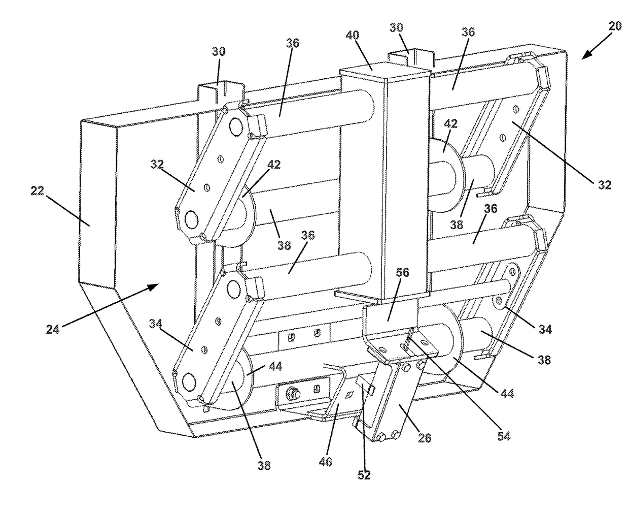
[0027]Referring now to FIGS. 4-6, the yield monitoring system (20) includes a four bar linkage type support assembly (24) providing translational movement of the strike plate (22) to transfer the force on the strike plate (22) to the load cell (26). The strike plate (22) includes spaced apart mounting brackets (30) with upper collars (42) and lower collars (44) receiving torsion tubes (38). Upper arms (32) and lower arms (34) are spaced apart at opposite ends of torsion tubes (36) and (38) and laterally outward from the mounting brackets (30). The torsion tubes (36) and (38) provide pivot axes for the linkage type support assembly (24) and include internal bearings at the arms (32) and (34). With support locations spaced vertically and laterally apart, the strike plate (22) is more broadly and evenly supported than single point supports of the prior art. The torsion tubes connect to a center generally vertically extending square mounting tube (40). The strike plate (22) therefore sw...

second embodiment

[0030]Referring now to FIGS. 7-13, the yield monitoring system (220) also includes a four bar linkage type support assembly (224) providing translational movement of a strike plate (222) to transfer the force on the strike plate (222) to a load cell (226). The strike plate (222) includes spaced apart mounting brackets (230) with upper collar type portions (242) and lower collar type portions (244) receiving torsion tubes (238). Upper arms (232) and lower arms (234) are spaced apart at opposite ends of torsion tubes (236) and (238) and laterally outward from the mounting brackets (230). The torsion tubes (236) and (238) provide pivot axes for the linkage type support assembly (224) and include internal bearings at the arms (232) and (234). With support locations spaced vertically and laterally apart, the strike plate (222) is more broadly and evenly supported than single point supports of the prior art. The upper of the torsion tubes (236 and 238) connect to spaced-apart center brace...


PUM


Abstract

A yield monitoring system for a grain harvester includes a large strike plate mounted on parallel four bar linkages. The strike plate intercepts a larger portion of the clean grain flow and is supported near the four corners to provide even translation and force transmission even if not struck in the center of the plate. The four bar linkages provide translational movement relative to a center load cell. An engagement bracket at the center of the strike plate includes a surface that is aligned perpendicularly to the sensing element of the load cell.

Description

BACKGROUND OF THE INVENTION[0001]Field of the Invention[0002]The present invention relates to a yield monitoring system and in particular to a load cell impact plate intercepting a portion of clean grain flow within a harvester.[0003]Description of the Prior Art[0004]Yield monitoring systems are commonly used for grain combines and other harvesters to determine the yield of the crop being harvested. Such systems typically use a small impact plate inserted downstream in the harvester and the clean grain flow path. The impact plate typically has an area of approximately four inches by six inches and deflects a portion of the flow. The impact of the flow being deflected places a load on the impact plate, which is transmitted to a load cell. The force measured by the load cell is calibrated so that the flow and therefore the yield can be calculated.[0005]Although such yield measurement systems may be satisfactory for many applications, there are problems. The small impact plate may not ...

Claims


Application Information

Patent Timeline
Patent Type & Authority Patents(United States)
IPC IPC(8): A01D75/00F16K15/03E03F7/04A01D43/08A01D41/127
CPCA01D75/00A01D41/127A01D41/1271A01D43/085E03F7/04F16K15/03Y10T137/7903
Inventor SCHLOESSER, CHRISTOPHER MBENNETT, ROBERT G
Owner OXBO INT CORP
Why Eureka
Try Eureka