Electrical plug connector

a technology of electrical plug connectors and plugs, applied in the direction of coupling contact members, coupling device connections, two-part coupling devices, etc., can solve the problems of how to improve the existing electrical plug connectors, and achieve the effect of improving the fixation between the electrical plug connector and the circuit board, and improving the structural strength of the electrical plug connector

Active Publication Date: 2017-05-09
ADVANCED CONNECTEK INC
View PDF5 Cites 0 Cited by
  • Summary
  • Abstract
  • Description
  • Claims
  • Application Information

AI Technical Summary

Benefits of technology

[0016]Based on the above, the legs of the positioning plate are located at the two sides of the base portion, extending from the bottom of the base portion, and assembled to the circuit board, so that the legs can be soldered with the circuit board, and the fixation between the base portion and the circuit board can be improved. As a result, the insulated housing would not detach from the circuit board easily when a bending test is applied to the electrical plug connector, and the tail portions of the upper-row plug terminals and the tail portions of the lower-row plug terminals would not detach from the circuit board. Consequently, the fixation between the insulated housing and the circuit board, and the structural strength of the electrical plug connector can be improved efficiently. In addition to the soldering between the plug terminals of the electrical plug connector and the contacts of the circuit board, the legs of the positioning plate are engaged with the circuit board, so that the fixation between the electrical plug connector and the circuit board can be further improved. Therefore, after the electrical plug connector is plugged or unplugged into an electrical receptacle connector for several times, the electrical plug connector would not be tilted with respect to the circuit board, so that the user can still conveniently built the connection between the plug and the receptacle. Moreover, the positioning plate increases the surface area of the insulated housing, thus electromagnetic interference and radiofrequency interference problems can be reduced.

Problems solved by technology

Consequently, how to improve the existing electrical plug connector becomes an issue.

Method used


Image

  • Electrical plug connector
  • Electrical plug connector
  • Electrical plug connector

Examples


Embodiment Construction

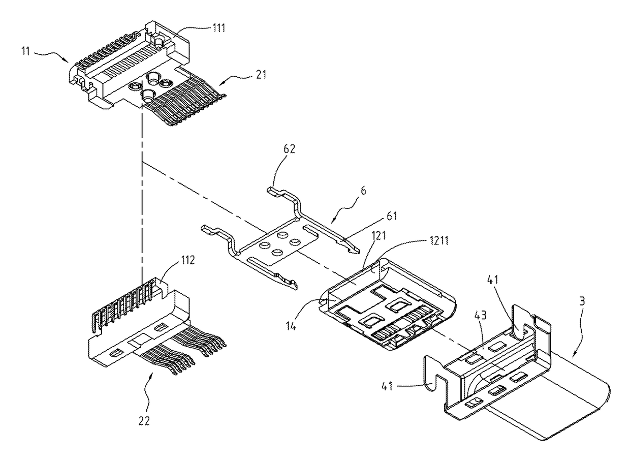
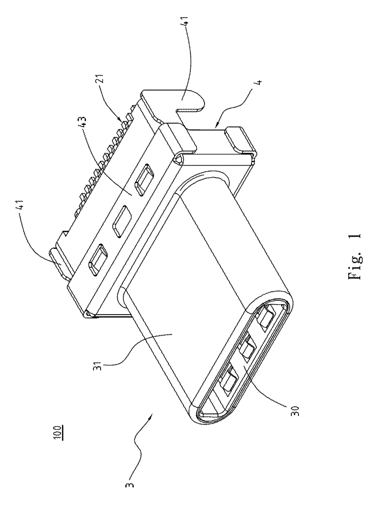
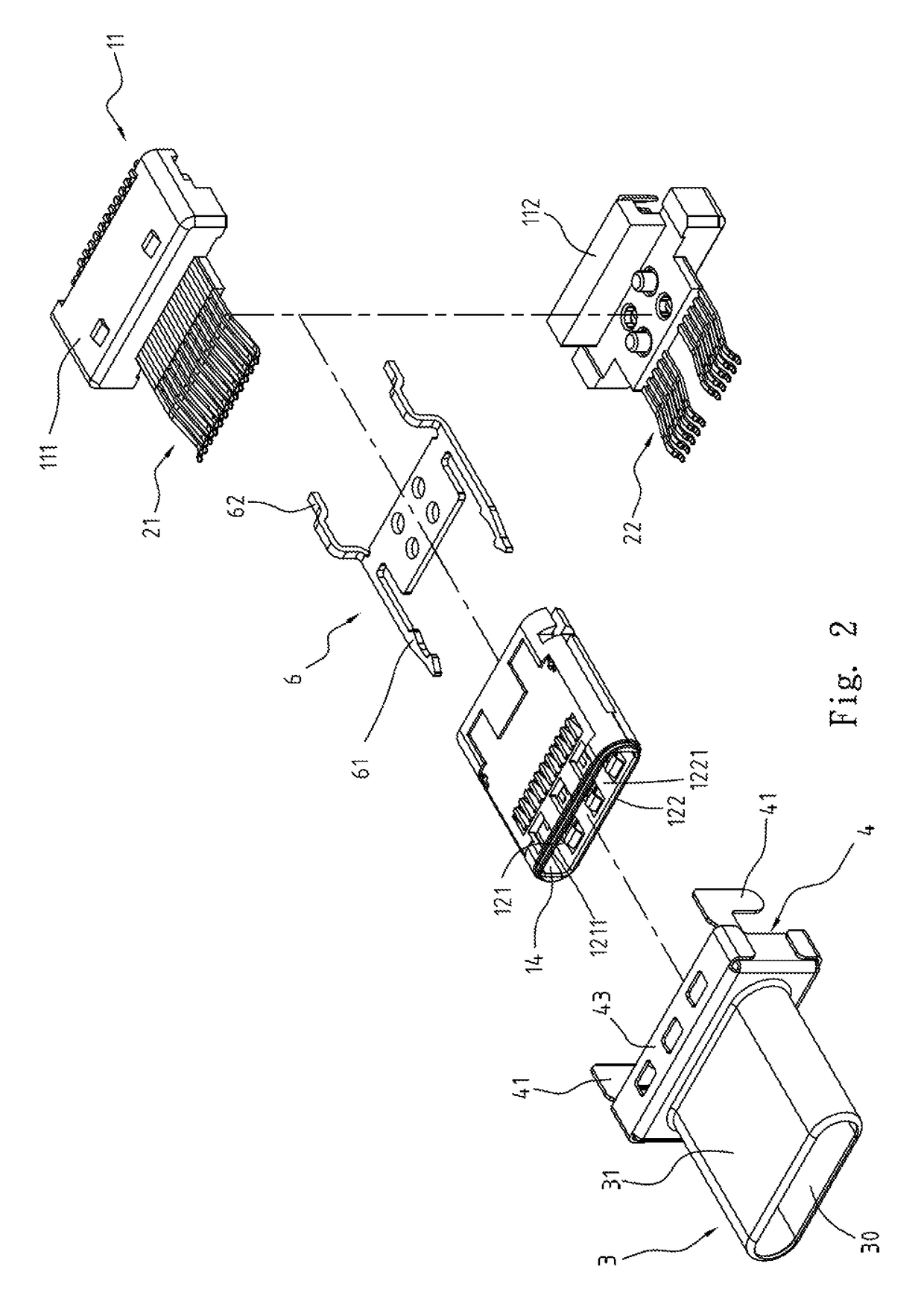
[0032]FIG. 1 illustrates a perspective view of an electrical plug connector 100 of, a first embodiment of the instant disclosure. FIG. 2 illustrates an exploded view (1) of the electrical plug connector 100 of the first embodiment of the instant disclosure. FIG. 3 illustrates an exploded view (2) of the electrical plug connector 100 of the first embodiment of the instant disclosure. FIG. 4 illustrates a side view of the electrical plug connector 100 of the first embodiment of the instant disclosure. Please refer to FIGS. 1 to 4, which illustrate an electrical plug connector 100 of a first embodiment of the instant disclosure. In this embodiment, the electrical plug connector 100 can provide a reversible or dual orientation USB Type-C connector interface and pin assignments, i.e., a USB Type-C plug connector. In this embodiment, the electrical plug connector 100 comprises an insulated housing 1, a plurality of plug terminals 2, a metallic shell 3, and a positioning plate 4. In this e...


PUM


Abstract

An electrical plug connector includes an insulated housing, a plurality of terminals, a metallic shell, and a positioning plate. The insulated housing includes a base portion, an upper portion, and a lower portion. The upper portion and the lower portion are extending from one side of the base portion. A mating room is between the upper portion and the lower portion. The terminals are held in the insulated housing. The metallic shell includes a tubular portion and a receiving cavity defined in the tubular portion. The insulated housing is received in the receiving cavity. The positioning plate is at the rear of the metallic shell to enclose the base portion. The positioning plate includes a first leg and a second leg respectively located at two sides of the base portion, so that the positioning plate can be assembled with a circuit board stably.

Description

CROSS-REFERENCES TO RELATED APPLICATIONS[0001]This non-provisional application claims priority under 35 U.S.C. §119(a) on Patent Application No. 201510103637.8 filed in China, P.R.C. on 2015 / 03 / 09, the entire contents of which are hereby incorporated by reference.FIELD OF THE INVENTION[0002]The instant disclosure relates to an electrical connector, and more particular to an electrical plug connector.BACKGROUND[0003]Generally, Universal Serial Bus (USB) is a serial bus standard to the PC architecture with a focus on computer interface, consumer and productivity applications. The existing Universal Serial Bus (USB) interconnects have the attributes of plug-and-play and ease of use by end users. Now, as technology innovation marches forward, new kinds of devices, media formats and large inexpensive storage are converging. They require significantly more bus bandwidth to maintain the interactive experience that users have come to expect. In addition, the demand of a higher performance b...

Claims


Application Information

Patent Timeline
Patent Type & Authority Patents(United States)
IPC IPC(8): H01R24/70H01R24/62H01R12/70H01R13/6585H01R12/71H01R12/72
CPCH01R12/7052H01R13/6585H01R24/62H01R12/716H01R12/724H01R12/707H01R13/04H01R12/722
Inventor TSAI, YU-LUNHOU, PIN-YUANLIAO, CHUNG-FUKAO, YA-FENZHOU, YANG-YANGCHEN, LONG-FEI
Owner ADVANCED CONNECTEK INC
Why Eureka
Try Eureka