
Battery pack secured by end plates

a technology of end plates and batteries, applied in the field of batteries, can solve the problems of difficult connection of battery holders, large volume of batteries, and large volume of batteries, and achieve the effect of efficiently cooling and widening the area

Inactive Publication Date: 2009-09-03
SANYO ELECTRIC CO LTD
View PDF0 Cites 45 Cited by
  • Summary
  • Abstract
  • Description
  • Claims
  • Application Information

AI Technical Summary

Benefits of technology

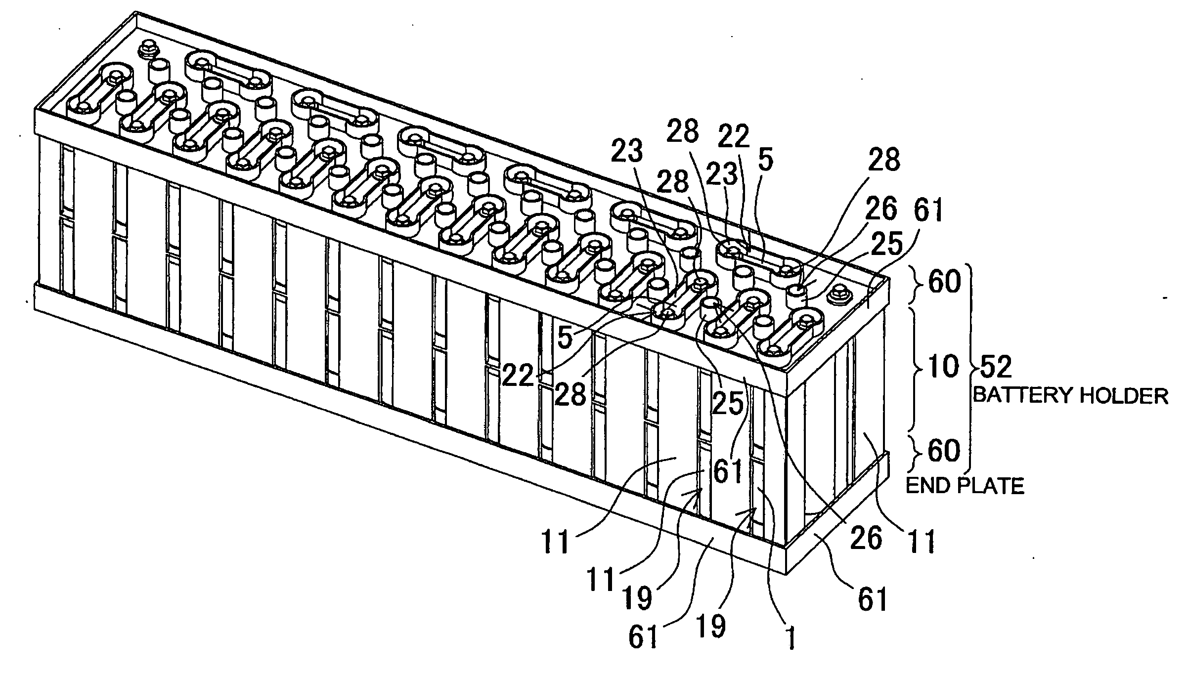
[0010]In the battery pack structured as above, effective utilization of the space defined between the cylindrical batteries enables the pair of end plates to be firmly secured to the battery holder. This is because the opposed walls are respectively provided with the thick portion projecting toward the swale between the adjacent cylindrical batteries, a through hole is defined in the thick portion, and thus the connection rod is inserted through the through hole to secure the end plate. Further, when the protrusion is provided so as to project toward the swale between the adjacent cylindrical batteries and the thick portion is provided to the opposed wall, such structure also realizes the characteristic of enabling the end plate to be firmly secured to the battery holder, without enlarging the contour of the peripheral wall while effectively utilizing the structure of efficiently cooling each of the batteries. This is because the provision of the protrusion to the opposed wall enables the inner surface of the opposed wall to approach the surface of the cylindrical battery so as to accelerate the velocity of the fluid flowing between the opposed wall and the cylindrical battery. Particularly, such structure carries the characteristic that because the connection rod is inserted through the thick portion made up by the protrusion for efficiently cooling the battery, the end plate can be firmly secured while the cylindrical batteries being disposed to be mutually closer and without the peripheral wall being enlarged.
[0012]In the battery pack of the present invention, a cooling gap 7 is defined between the opposed wall 12 and the cylindrical battery 1 to cause the fluid to flow for cooling the battery, and thus the cylindrical battery can be efficiently cooled in a wider area.
[0013]In the battery pack of the present invention, a cooling medium is forcibly blown through the through hole 16 to cool the cylindrical battery 1 in the storage portion 13, and thus the cylindrical battery can be efficiently cooled via the battery holder.
[0015]Further, in the battery pack of the present invention, the end plate 20 can be so structured as to have an insertion retainer 27 for inserting and retaining the end of the cylindrical battery 1 in a fixed position, the cylindrical battery 1 being accommodated in the storage portion 13 of the holder main body 10. The battery pack enables the cylindrical battery to be disposed in a fixed position by means of the end plate. Particularly in this structure, when so structured as to have a cooling gap around the surface of the cylindrical battery, the cylindrical battery can have an accurate cooling gap around the surface of the cylindrical battery for an efficient cooling operation.

Problems solved by technology

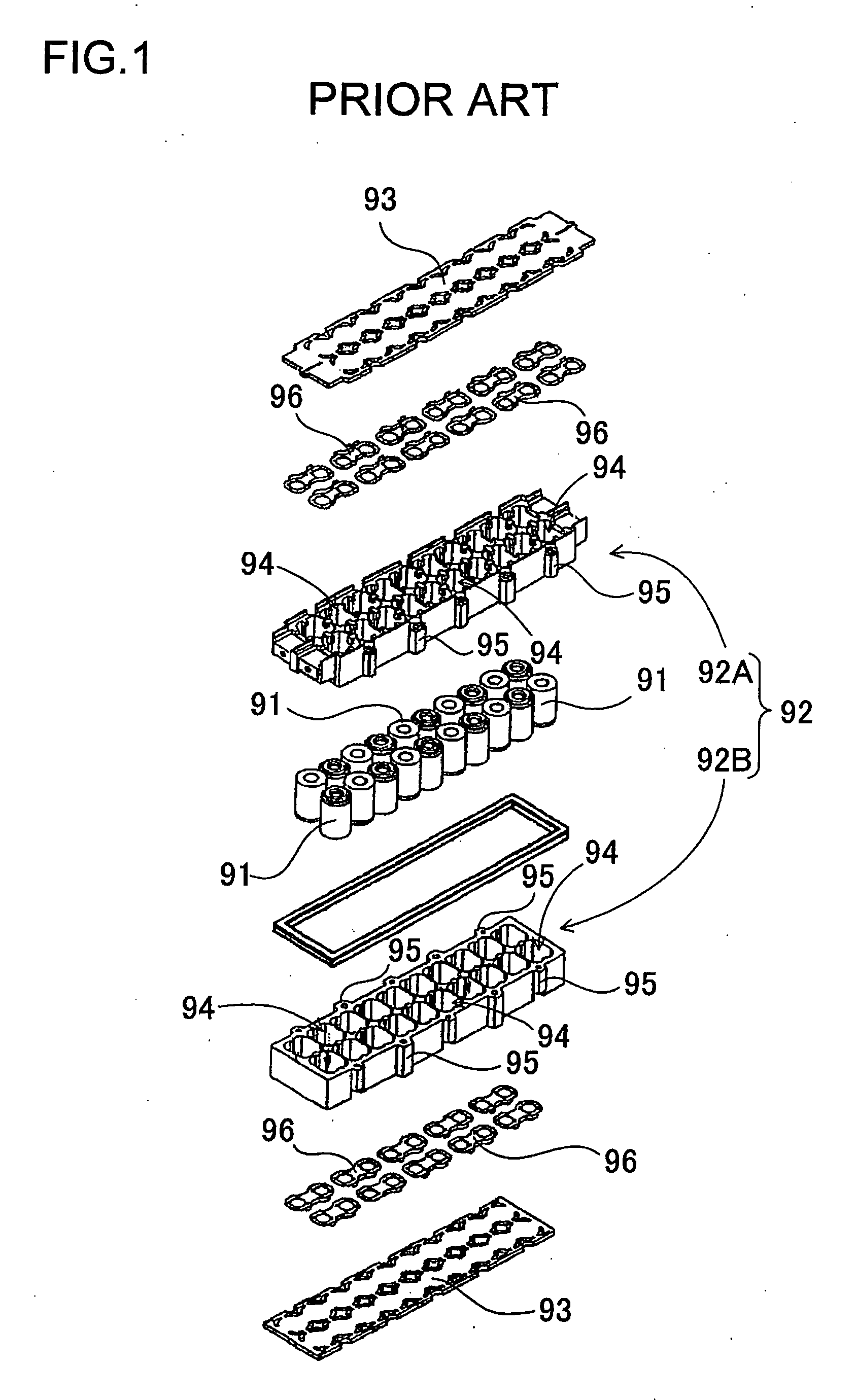
The battery holder 92 thus structured is disadvantageous in that its contour becomes larger due to the structure of having the connection member.
Further, since the battery holder 92 is welded to be connected with the end plate 93, the structure of accommodating the multitude of batteries suffers the disadvantage that it is difficult to connect the battery holder 92 and the end plate 93 in a firm, strong manner.
In particular, since the battery holder 92 and the end plate 93 are connected by welding the peripheral edge of the end plate 93 in joint with the periphery of the opening of the battery holder 92, such arrangement suffers the disadvantage that connection strength becomes weaker at the center portion of the end plate 93.
The wider an interval between the welded portions where the battery holder and the opposing end plate are mutually welded, the weaker the mechanical strength of such structure in aiming at firmly securing the end plate to the battery holder.
To avoid such disadvantage, if the end plate is to be formed thicker in obtaining a wider welded portion, such formation will inevitably involve a higher cost of manufacture as well as a heavier and larger structure.

Method used


Image

  • Battery pack secured by end plates
  • Battery pack secured by end plates
  • Battery pack secured by end plates

Examples


Embodiment Construction

)

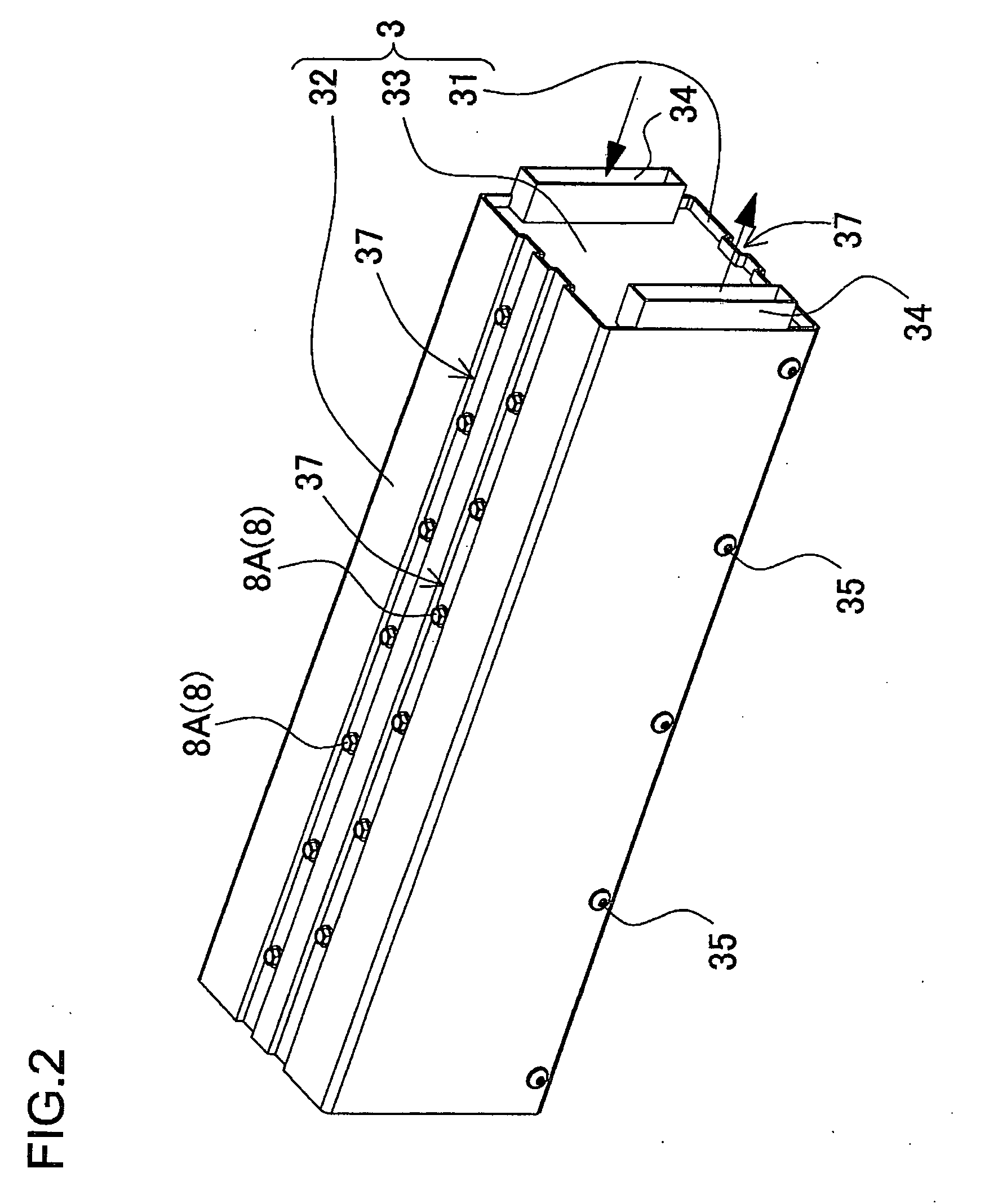
[0028]The battery pack shown in FIG. 2 through FIG. 8 includes a plurality of cylindrical batteries 1 and a plastic-made battery holder 2 accommodating the plurality of cylindrical batteries 1 disposed in a matrix or offset arrangement in a mutually parallel posture. Further, the battery pack shown in FIGS. 2, 3, 7 and 8 includes an outer casing 3 for accommodating the battery holder 2, and a cooling duct 4 is provided between the outer casing 3 and the battery holder 2.

[0029]The cylindrical battery 1 to be used can be any kind of rechargeable battery such as a nickel-hydrogen battery and a lithium-ion battery. The cylindrical battery 1 shown in FIG. 8 is composed of two pieces of unit cells 1A interconnected linearly, and has terminal electrodes 6 secured at the opposite ends, to which a bus bar 5 is connectable. It is also practical and practicable that the cylindrical battery 1 is composed of either a single piece of battery or three or more pieces of batteries.

[0030]The outer c...


PUM


Abstract

In the battery pack, a battery holder accommodates a plurality of cylindrical batteries disposed in a matrix or offset arrangement in a mutually parallel posture. The battery holder includes a holder main body and an end plate respectively connected to opposite ends of the holder main body having a plurality of opposed walls disposed in a mutually parallel posture inside peripheral walls, and also having a storage portion accommodating the cylindrical batteries between the opposed walls. The opposed wall is provided, on its opposite faces, with a protrusion projecting toward the swale between the adjacent cylindrical batteries to constitute a thick portion defining a through-hole extending through in the longitudinal direction of the cylindrical battery. A connection rod is inserted in the through-hole defined in the above-mentioned thick portion, and the end plate is secured to the opposite ends of the holder main body by means of the connection rod.

Description

BACKGROUND OF THE INVENTION[0001]1. Field of the Invention[0002]The present invention relates to a battery pack where a plurality of cylindrical batteries are contained in a battery holder and disposed in a fixed position, and particularly to a battery pack which is optimal as a power source mounted on a vehicle to supply electric power to a motor for driving the vehicle.[0003]2. Description of the Related Art[0004]Like in the case of a power source for a vehicle, a battery pack requiring larger output power has a multitude of batteries connected in series or in parallel. In order to retain the multitude of batteries in a fixed position, such battery pack is accommodated in a plastic-made battery holder. In order to accommodate the multitude of batteries in multiple tiers or rows, the battery holder accommodates the batteries disposed in a matrix or offset arrangement in a mutually parallel posture. The battery holder accommodating the multitude of batteries is so shaped as to have ...

Claims


Application Information

Patent Timeline
IPC IPC(8): H01M2/10H01M2/36H01M10/60H01M10/613H01M10/625H01M10/643H01M10/6557H01M10/6563H01M50/213H01M50/224H01M50/291H01M50/293
CPCH01M2/1077H01M10/5004H01M10/5016H01M10/5073H01M10/5063H01M10/5067H01M10/503H01M10/625H01M10/6563H01M10/643H01M10/6561H01M10/6566H01M10/613Y02E60/10H01M50/293H01M50/224H01M50/213H01M50/291
Inventor FUJII, KAZUHIRO
Owner SANYO ELECTRIC CO LTD
Learn More