Circuit structural body and method for manufacturing the same

a technology of circuit structure and manufacturing method, which is applied in the direction of printed circuit non-printed electric components association, electrical apparatus construction details, printed element electric connection formation, etc., can solve the problems of complex structure used for heat dissipation, complex assembly of the entire electric connection box, and insufficient downsizing of the entire structure, etc., to achieve superior heat dissipation and manufacturing circuit structure body efficiently

Active Publication Date: 2006-12-26
AUTONETWORKS TECH LTD +2
View PDF8 Cites 45 Cited by
  • Summary
  • Abstract
  • Description
  • Claims
  • Application Information

AI Technical Summary

Benefits of technology

[0010]In view of such circumstances, it is an object of the present invention to provide a circuit structural body in which a power circuit including a semiconductor switching element su

Problems solved by technology

Therefore, although a relay-type electric connection box in the related art may be downsized by introducing the FET, the entire structure is too complicated to realize sufficient downsizing and, in particular, reduction of the height continues to be an important task.
Since the FET is interposed between the bus-bar board and the printed circuit board in the electric connection box, heat generated by the FET is liable to stay bet

Method used


Image

  • Circuit structural body and method for manufacturing the same
  • Circuit structural body and method for manufacturing the same
  • Circuit structural body and method for manufacturing the same

Examples


Embodiment Construction

[0037]Referring now to the drawings, a preferred embodiment of the present invention will be described. In this embodiment, a method of manufacturing a circuit structural body constituting a distributing circuit for distributing an electric power supplied from a common power source mounted on a vehicle or the like to a plurality of electric loads will be described. However, the application of the circuit structural body of the present invention is not limited thereto, and may be widely applied to the case in which ON / OFF switching of the power circuit is performed by the semiconductor switching element.

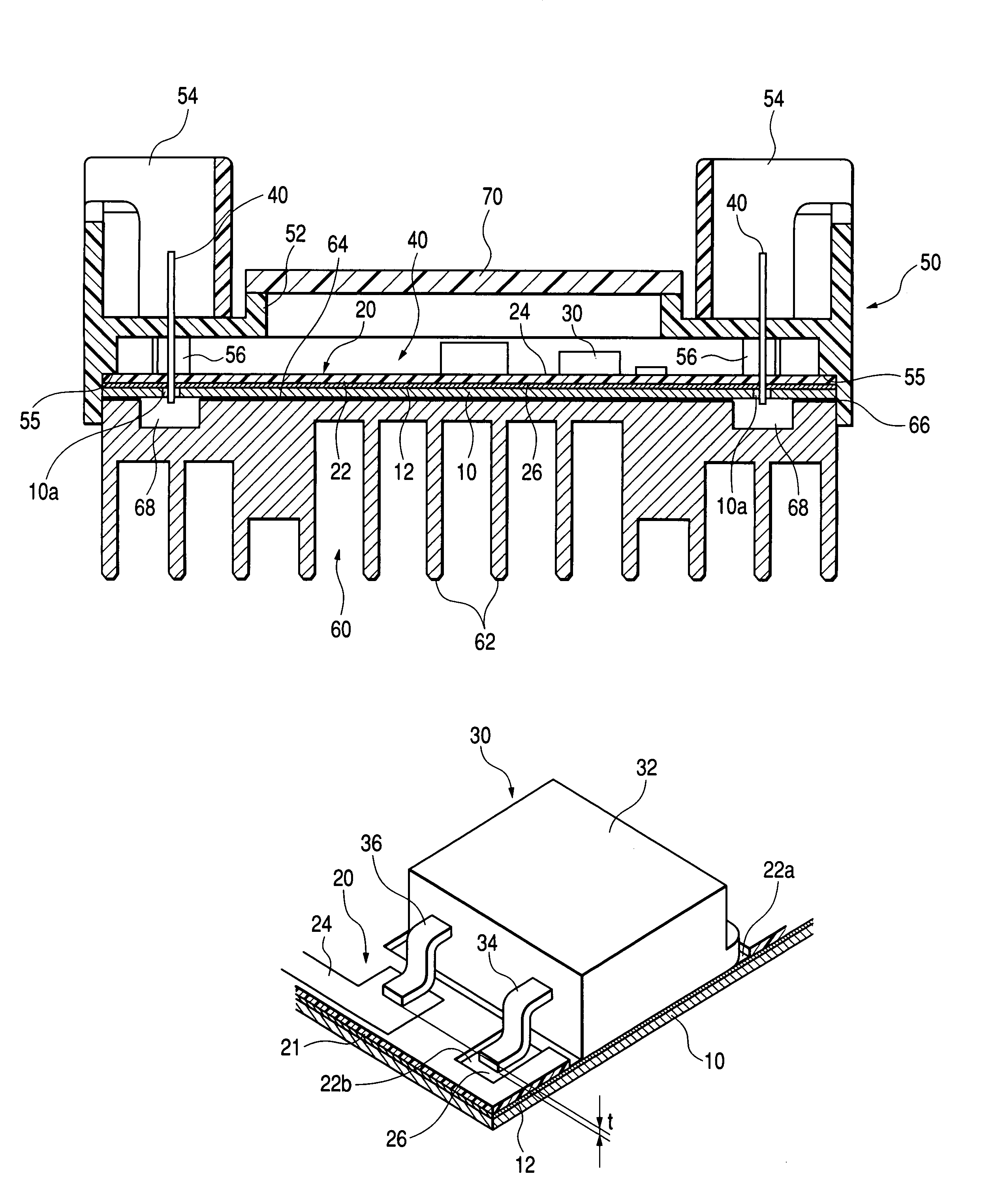
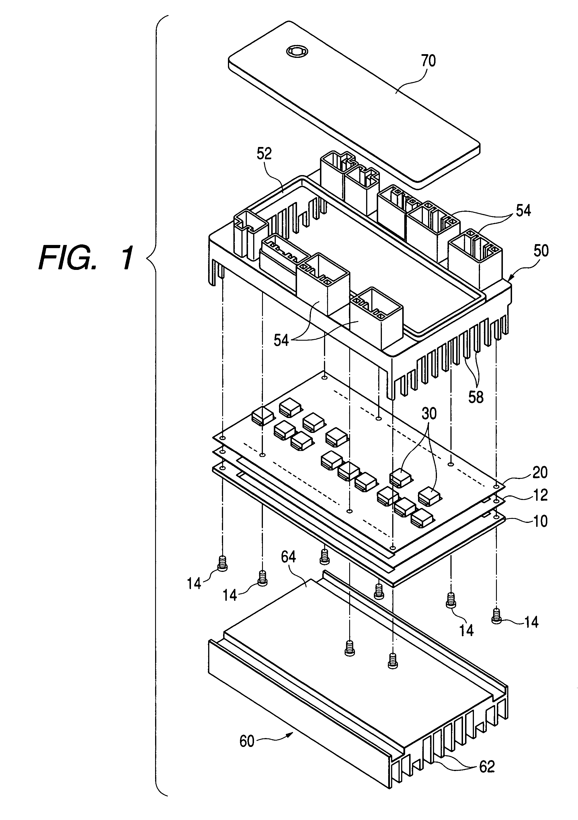
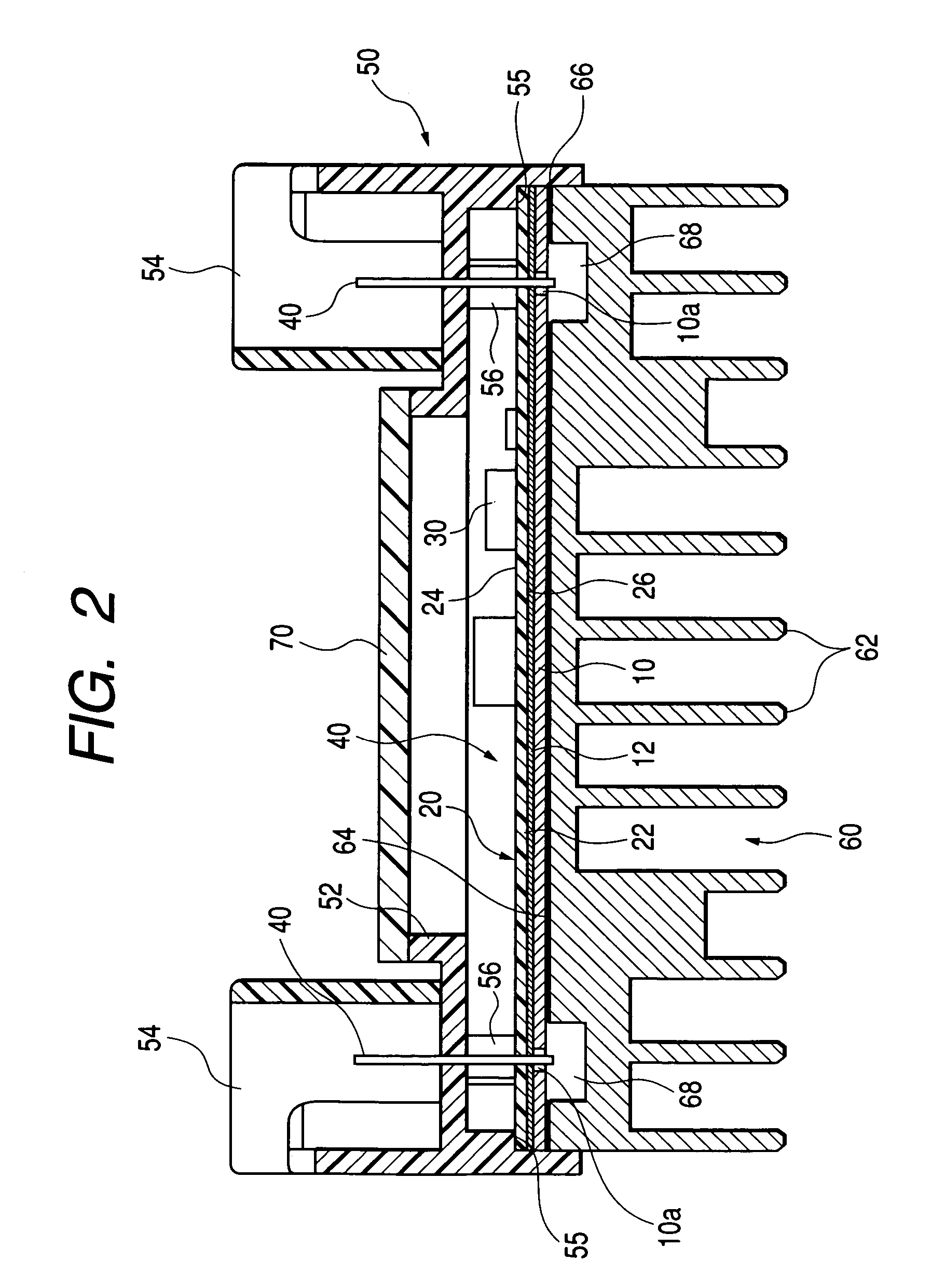
[0038]FIG. 1 and FIG. 2 show the entire structure of the circuit structural body according to the present embodiment. The circuit structural body includes a single printed circuit board 20, a plurality of semiconductor switching elements (FET 30 in the drawing), a plurality of terminal pins 40, an insulating case 50, and a heat dissipating member 60.

[0039]The printed circuit board 20 ...


PUM


Abstract

A circuit structural body includes a printed circuit board having a conductive pattern constituting a power circuit including a semiconductor switching element and disposed on one surface of the printed circuit board, and a conductive pattern constituting a control circuit for controlling the semiconductor switching element and disposed on the other surface of the printed circuit board. The printed circuit board has a through-hole for mounting the semiconductor switching element to both of the conductive patterns. The circuit structural body can be manufactured by a method including the step of laminating a reinforcing plate to one surface of the printed circuit board and the step of mounting the semiconductor switching element from the opposite side to the reinforcing plate.

Description

BACKGROUND OF THE INVENTION[0001]1. Field of the Invention[0002]The present invention relates to a circuit structural body provided with a combination of a bus-bar which constitutes a power circuit and a printed circuit board for controlling drive of a semiconductor switching element provided in the power circuit, and a method of manufacturing the same.[0003]2. Description of the Related Art[0004]In the related art, as means for distributing electric power to the respective electronic units from a common vehicle-mounted power source, an electric connection box in which a power distributing circuit formed by laminating a plurality of bus-bar boards is provided and a fuse and a relay switch are built in the circuit is generally known.[0005]In addition, in order to realize downsizing of such electric connection box and high-speed switching control, a structure in which a semiconductor switching element such as FET is interposed between an input terminal and an output terminal in stead ...

Claims


Application Information

Patent Timeline
IPC IPC(8): H05K7/20H05K1/11H05K1/02H05K1/18H05K3/40
CPCH05K1/0203H05K1/0265H05K7/20854H05K3/0061H05K2201/0352H05K2201/0394H05K2201/094H05K2201/09472H05K2201/10166
Inventor KOBAYASHI, TAKEHITO
Owner AUTONETWORKS TECH LTD
Why Eureka
Try Eureka