Signal processor

a signal processor and processor technology, applied in pulse manipulation, pulse technique, instruments, etc., can solve the problems of increasing the cost of the radar apparatus, erroneous detection as a target, and difficulty in downsizing the radar apparatus, so as to prevent oscillation, avoid erroneous detection, and prevent the effect of erroneous detection

Active Publication Date: 2017-05-09
FUJITSU GENERAL LTD
View PDF7 Cites 4 Cited by
  • Summary
  • Abstract
  • Description
  • Claims
  • Application Information

AI Technical Summary

Benefits of technology

[0010]Since the controller can detect the presence or absence of an abnormality in the output voltage of the power source, it is possible to avoid erroneous control caused by an abnormality or the like, and to perform appropriate control.
[0011]Therefore, an object of the invention is to provide the technology for preventing the oscillation due to an abnormality in the power output and the erroneous detection due to a switching noise without providing a new configuration.

Problems solved by technology

As a result, there is a possibility that they are erroneously detected as a target.
Meanwhile, in the case where a special oscillation prevention configuration is provided in the power circuit, or where a configuration for detecting a switching noise and for suppressing the noise generation is separately provided, there is a problem that the cost of the radar apparatus is increased and downsizing of the radar apparatus becomes difficult.

Method used


Image

  • Signal processor
  • Signal processor
  • Signal processor

Examples


first embodiment

1. First Embodiment

[0035]

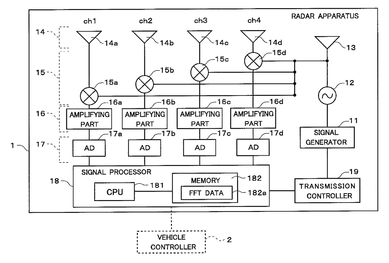
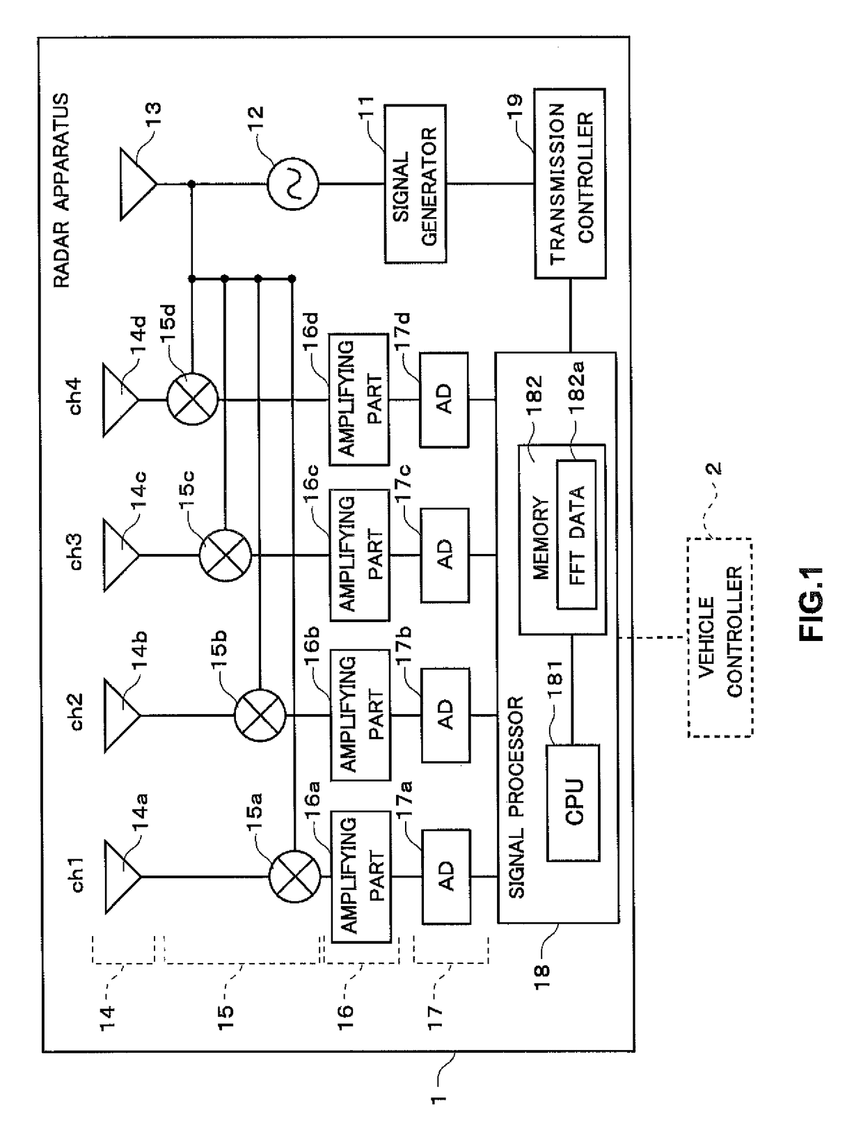
[0036]First, the configuration of a radar apparatus 1 of the invention is explained. FIG. 1 is a block diagram that shows a schematic configuration of the radar apparatus 1. The radar apparatus 1 is mainly provided in the vicinity of a bumper in front of a vehicle. The radar apparatus 1 scans a predetermined scanning range at one scanning, and derives a distance between the vehicle and a target. The radar apparatus 1 also derives a speed of the target, and relative velocity which is the speed of the target relative to the speed of the vehicle. Information such as the derived distance is output to a vehicle controller 2, and the vehicle controller 2 performs a variety of control based on the input information.

[0037]The radar apparatus 1 includes a signal generator 11, an oscillator 12, a transmission antenna 13, a receiving antenna 14, a mixer 15, an amplifying part 16, an AD (Analog to Digital) converter 17, a signal processor 18, and a transmission controll...

second embodiment

2. Second Embodiment

[0068]Next, the second embodiment is explained. In the first embodiment, the configuration for preventing the erroneous detection of the target by stopping the radar apparatus in the case where there is an abnormality in the power output is explained. However, the invention may have a configuration for preventing the erroneous detection of the target without stopping the radar apparatus (That is, while performing the target derivation processing). Therefore, in the second embodiment, a method by which the radar apparatus prevents the erroneous detection of the target while performing the target derivation processing is explained.

[0069]

[0070]A radar apparatus 1 of the second embodiment has almost the same configuration as that of the radar apparatus 1 shown in FIG. 1. Therefore, the explanation about the configuration of the radar apparatus 1 of the second embodiment is omitted.

[0071]

[0072]Processing of the radar apparatus 1 of the second embodiment is explained. ...

fourth embodiment

4. Fourth Embodiment

[0111]Next, the fourth embodiment is explained. In the embodiments described above, the case where there is an abnormality in the power output is explained as an example. However, for example, in the case where a switching power supply is used as a power supply, even when there is no abnormality in the power output, noise due to switching is superimposed on a beat signal, and a peak signal caused by the switching noise may be erroneously detected as a target. Therefore, in the fourth embodiment, the configuration for preventing this is explained.

[0112]

[0113]A radar apparatus 1 of the fourth embodiment also has almost the same configuration as that of the radar apparatus 1 shown in FIG. 1. Therefore, the explanation about the configuration of the radar apparatus 1 of the fourth embodiment is omitted.

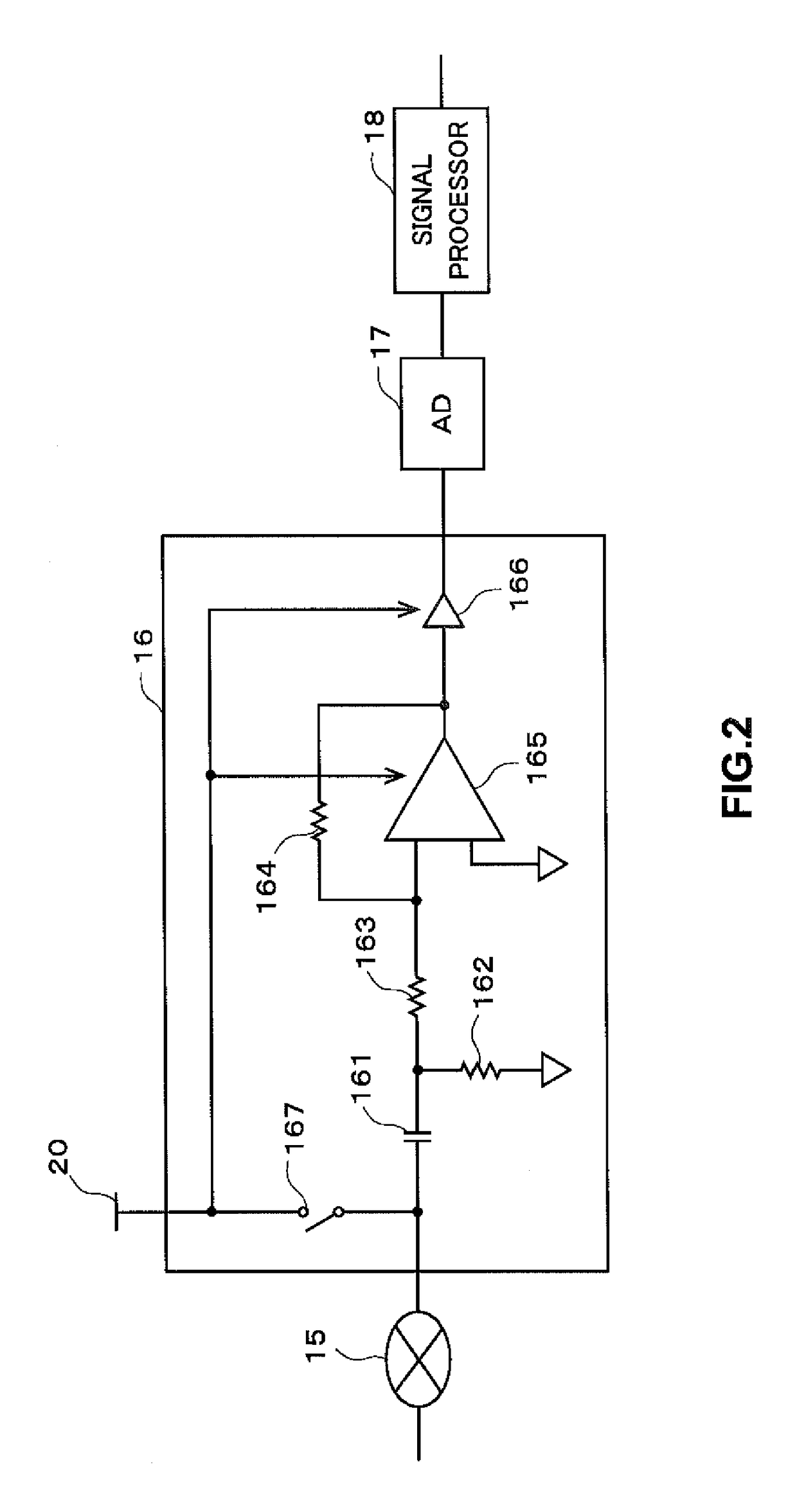
[0114]In addition, the configuration of an amplifying part 16 of the fourth embodiment is almost the same as that of the amplifying part 16 shown in FIG. 2. However, a...


PUM


Abstract

A signal processor includes an amplifier that amplifies a control signal which is input into the amplifier to output an amplified control signal; and a controller that performs predetermined control based on the amplified control signal. When the control signal is not input into the amplifier, the amplifier amplifies a voltage signal input from a power source for driving the amplifier.

Description

BACKGROUND OF THE INVENTION[0001]Field of the Invention[0002]The invention relates to a signal processor and a radar apparatus.[0003]Description of the Background Art[0004]Conventionally, a radar apparatus installed in a vehicle or the like transmits a transmission wave from a transmission antenna, receives a reflected wave from a target at a receiving antenna, and derives a target location to the vehicle (radar apparatus). The reflected wave from the target becomes a minuter signal as the distance from the target is farther. Therefore, the radar apparatus has a configuration considering low noise so that a received signal is not buried in the noise generated in the circuit in the radar apparatus, and so as to surely derive even a distant target.[0005]However, when oscillation of output due to an abnormality in a power circuit in the radar apparatus or a switching noise is generated, they are calculated as a peak depending on the oscillation frequency, a frequency of the noise, or t...

Claims


Application Information

Patent Timeline
Patent Type & Authority Patents(United States)
IPC IPC(8): G01S13/02H03K5/1252G01S7/40G01S7/35G01S13/93G01S13/931
CPCH03K5/1252G01S7/354G01S7/4021G01S13/02G01S13/931G01S2007/356G01S7/356
Inventor IWAI, KENTAENOMOTO, DAISUKEKOMATSU, KAZUHIRO
Owner FUJITSU GENERAL LTD
Why Eureka
Try Eureka