Rotary impingement cleaning device with replaceable cartridge gear train

Active Publication Date: 2017-05-16
ALFA LAVAL ASHBROOK SIMON HARTELY INC
View PDF9 Cites 1 Cited by
  • Summary
  • Abstract
  • Description
  • Claims
  • Application Information

AI Technical Summary

Benefits of technology

The present invention provides a rotary impingement cleaning apparatus with a gear train enclosed in a cartridge. The gear train has multiple stages of planetary gear clusters with input and output shafts connected thereto. The cartridge surrounds a channel for a flow of pressurized cleaning liquid. The apparatus has a set of rotating nozzles for providing lubrication to the gears. The technical effect of the invention is that it allows for easy replacement of the gear train without the need for extensive maintenance or downtime.

Problems solved by technology

The gears are therefore subjected to substantial stress and will, over time, wear and malfunction.
The process of replacing gears and related parts in this fairly intricate apparatus involves time and skill.
Often, the user of the rotary impingement cleaning apparatus will entrust the part replacement function to the apparatus manufacturer, placing the apparatus out of service for an extended period of time.

Method used


Image

  • Rotary impingement cleaning device with replaceable cartridge gear train
  • Rotary impingement cleaning device with replaceable cartridge gear train
  • Rotary impingement cleaning device with replaceable cartridge gear train

Examples


Embodiment Construction

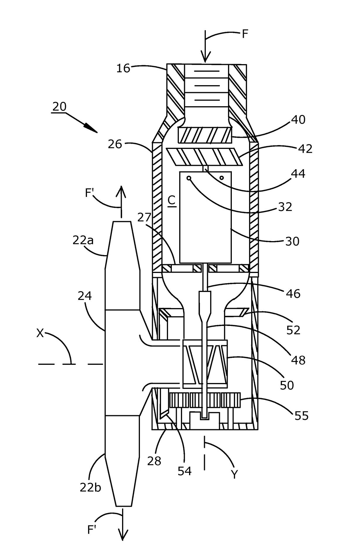
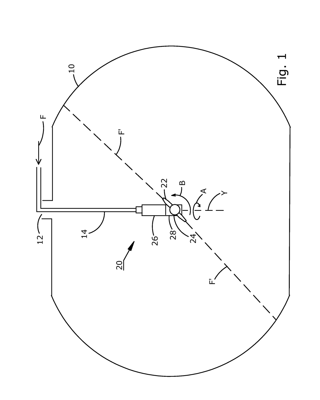
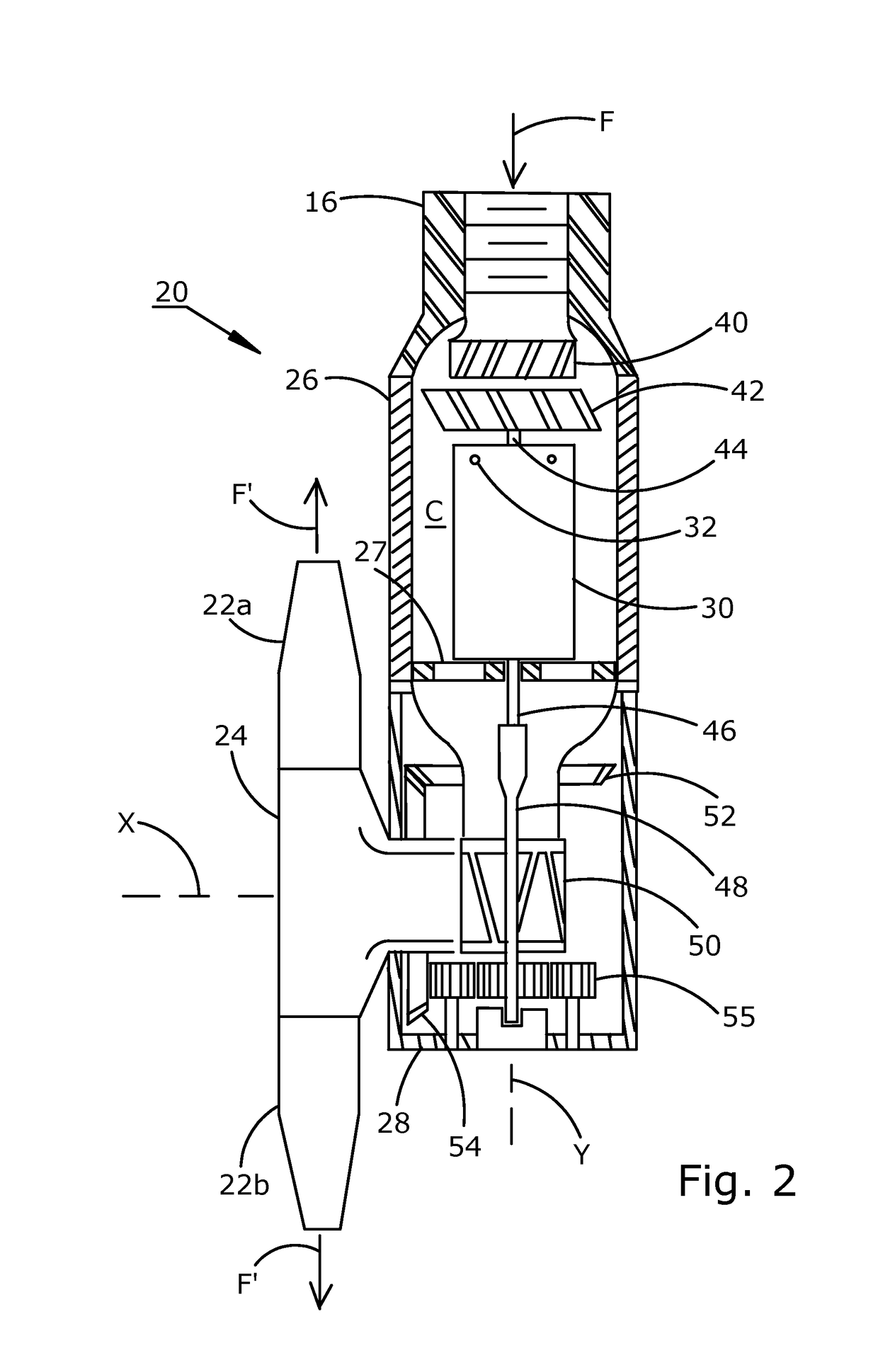
[0011]Referring to FIG. 1, a storage vessel 10 is shown in schematic front elevation view with a rotary impingement cleaning apparatus 20 suspended therein. An inlet pipe 14 passes into vessel 10 through access port 12 and suspends cleaning apparatus 20 in the approximate center of vessel 10. Inlet pipe 14 also serves to supply a flow of pressurized cleaning liquid F to cleaning apparatus 20. Flow F of pressurized cleaning liquid travels through a stationery body housing 26 of cleaning apparatus 20, while driving rotary housing 28 to rotate around the Y axis in the direction indicated by arrow A. Internal gearing in rotary housing 28 causes nozzles 22 to simultaneously rotate about the X axis (not shown) in the direction indicated by arrow B, discharging opposed outlet flows F′ of cleaning liquid to impinge the interior wall of vessel 10, effectively cleaning the interior vessel wall. The residual cleaning liquid at the bottom of vessel 10 may be removed by gravity drain or by sucti...


PUM


Abstract

The invention provides a rotary impingement cleaning apparatus including a gear train contained within a cartridge for easy installation and removal as a unit. The cleaning apparatus has an internal support platform to hold the cartridge and gear train. The platform is mounted within a fixed body housing. An output shaft from the cartridge gear train drives a rotary housing that drives a nozzle housing to rotate the nozzles around the horizontal axis.

Description

FIELD OF THE INVENTION[0001]The present invention relates to the field of rotary impingement cleaning apparatus, and more particularly to a rotary impingement cleaning apparatus having a gear train contained in a cartridge that is replaceable as a unit.BACKGROUND OF THE INVENTION[0002]A rotary impingement cleaning apparatus generally operates by discharging a high pressure flow of a cleaning liquid through rotating nozzles to impinge and clean the inner wall of a container or vessel. The body of the cleaning apparatus is rotated around a first axis while the nozzles rotate around a second axis, the second axis being oriented angularly to the first axis, often in perpendicular relation. Depending on the particular container or vessel and the stored materials therein, the cleaning liquid will be drained or recycled through filtration apparatus.[0003]With high pressure liquid flowing through the cleaning apparatus, the liquid also strongly impacts internal parts of the apparatus causin...

Claims


Application Information

Patent Timeline
IPC IPC(8): B08B3/02B05B3/04B08B9/093
CPCB08B3/02B08B9/0936B05B3/0445B05B3/0459
Inventor DELANEY, ROBERT E.DELANEY, ANDREW K.MARCH, III, JOHN H.MORGAN, CHADSTEWART, GEORGE E.
Owner ALFA LAVAL ASHBROOK SIMON HARTELY INC
Why Eureka
Try Eureka