
Collapsible reusable pallet

a reusable, pallet technology, applied in the field of pallets, to achieve the effect of convenient disassembly, exceptional structural strength, and improved sanitation

Active Publication Date: 2020-03-17
RMC JONES
View PDF34 Cites 0 Cited by
  • Summary
  • Abstract
  • Description
  • Claims
  • Application Information

AI Technical Summary

Benefits of technology

The invention is a pallet that uses a unique frame and top deck structure to provide exceptional strength and sanitation. It reduces the number of stringers or slats used in conventional wooden pallets and can be easily disassembled for compact storage and transport. The pallet is designed to be reassembled and offers a cost savings advantage over traditional pallets. The fabric covering the deck surface gaps provides structural strength and prevents debris or dislodged material from falling into the container during shipment. The pallet can also be equipped with load centering devices to help distribute the load evenly. The invention offers a strong, cost-effective alternative to traditional pallets.

Problems solved by technology

Collapsibility of the pallet enables multiple storage, reuse and shipment cycling of the pallet, which has not been economically available with prior rigid pallet designs.

Method used


Image

  • Collapsible reusable pallet
  • Collapsible reusable pallet
  • Collapsible reusable pallet

Examples


first embodiment

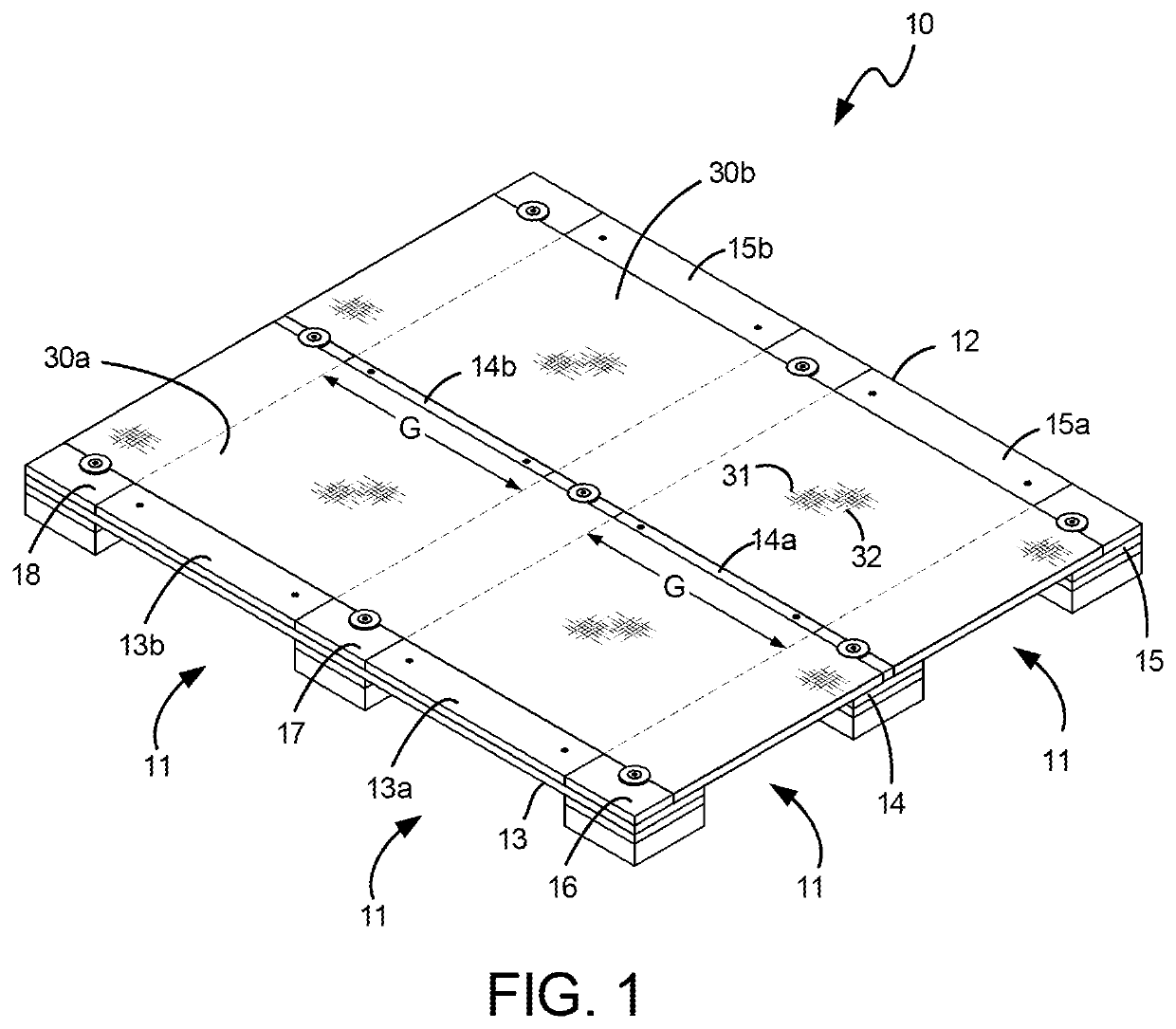
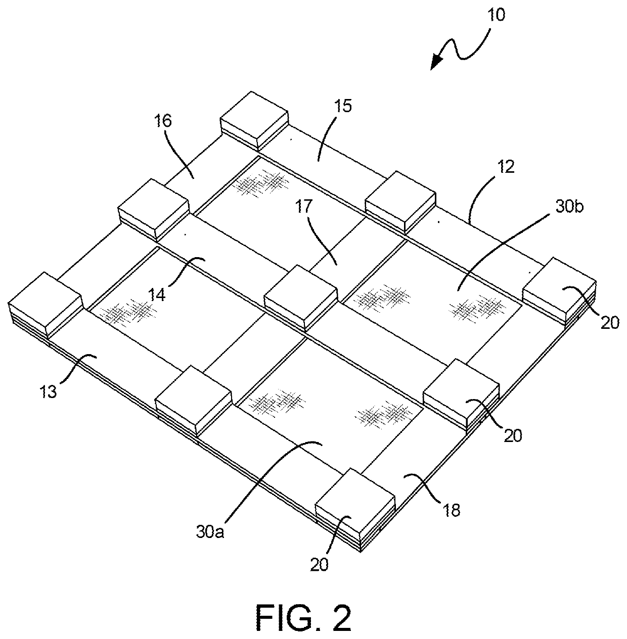
[0045]an operatively assembled pallet arranged and configured according to the principles of this invention is diagrammatically illustrated at 10 in FIGS. 1 and 2. The pallet 10 has an interlocked wooden upper frame 12 supported by nine aligned and spaced legs 20 which support the upper frame above a floor or other support surface (not illustrated) at a height sufficient to enable projecting lifting tines or arms of a Forklift or hand operated pallet jack to be inserted into the void spaces formed between the lower surface of the frame 12 and the floor / support surface and between adjacent aligned outer and middle legs, as illustrated by the arrows 11 in FIG. 1. In the pallet embodiment illustrated, such lifting tines or arms can be inserted within the receptor spaces 11 from any of the four sides of the pallet (i.e. four-way access) for lifting and moving the pallet.

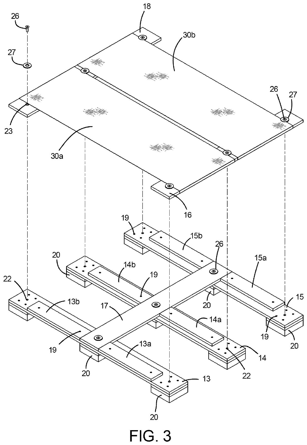
[0046]The frame 12 construction is described in greater detail with reference to FIGS. 3-6. It will be understood that...

third embodiment

[0064]Use of a sheet material as a structural member for increasing the entire or selected portions of the pallet deck surface strength is not limited to collapsible pallet configurations. Use of a sheet material to strengthen the load capacity of a pallet, whether a woven or non-woven fabric type of material, is also advantageous in the construction of non-collapsible solid frame pallet constructions. An example of a pallet 60, which incorporates the same basic interlocking frame construction as shown in prior embodiments, except that the frame members are rigidly secured together and not collapsible, is illustrated in FIGS. 15, 16 and 18. The various elements of the pallet 60 have the same numerical designations as those of the previously described pallet embodiments, with an additional prime (′) designation.

[0065]Referring to FIGS. 15, 16 and 18, the lateral frame members 16′, 17′ and 18′ are rigidly secured to the underlying longitudinal frame members 13′, 14′ and 15′ by means o...


PUM


Abstract

A pallet for supportively carrying and transporting goods as a unit load in a stable efficient manner is disclosed. The pallet can be configured as a rigid or easily disassemblable compact collapsed structure. Interlocking frame members form an upper planar surface with one or more gap or void areas. A sheet of flexible material operatively secured to the frame is tautly stretched to overlie the void areas and forms a structural part of the upper planar surface to counteract downward load forces applied to the fabric over the pallet surface void areas. The sheet material preferably comprises woven polypropylene material.

Description

[0001]This application claims priority from U.S. Provisional Patent Application Ser. No. 62 / 623,597 filed in the U.S. Patent and Trademark Office on Jan. 30, 2018 by Robert J. Jones et al. and entitled FOLDABLE / COLLAPSIBLE REUSABLE PALLET, the entire contents of which are herein incorporated by reference.FIELD OF THE INVENTION[0002]This invention relates generally to a pallet, which is defined as a portable flat rigid platform structure used as a base for assembling, storing, stacking, handling and transporting goods as a unit load in a stable efficient fashion. More particularly, the invention relates to a pallet having a unique frame and top deck structure incorporating a continuous cover sheet of material providing structural strength, improved sanitation, and enables the pallet to be repeatedly collapsed and compacted for transport and readily reassembled again for use.BACKGROUND[0003]Pallets are universally used in virtually all industries. Most industrial pallets are rigidly c...

Claims


Application Information

Patent Timeline
Patent Type & Authority Patents(United States)
IPC IPC(8): B65D19/00B65D19/36B65D19/38
CPCB65D19/0097B65D19/38B65D19/0069B65D19/36B65D19/0075B65D2519/00044B65D2519/0087B65D2519/00815B65D2519/00985B65D2519/00029B65D2519/0099B65D2519/00064B65D2519/00273B65D2519/00323B65D2519/00034B65D2519/00343B65D2519/00238B65D2519/00293B65D2519/00338B65D2519/00567B65D2519/00572Y02W30/80
Inventor JONES, ROBERT J.JONES, MICHAEL R.
Owner RMC JONES
Learn More