
Display device

a display device and gate length technology, applied in static indicating devices, instruments, non-linear optics, etc., can solve the problems of difficult reduction of the distance between respective source electrodes or drain electrodes adjacent to each other in the gate length direction adjacent to each other and the plurality of transistors including the transistors arranged in the gate length direction cannot be closely arranged

Active Publication Date: 2017-05-16
JAPAN DISPLAY INC
View PDF7 Cites 0 Cited by
  • Summary
  • Abstract
  • Description
  • Claims
  • Application Information

AI Technical Summary

Benefits of technology

The present invention aims to provide a display device that can reduce the area around the display region where a plurality of transistors are located. This is achieved by arranging the transistors in a way that their gate width is larger than their gate length. This arrangement allows for efficient use of space and minimizes the area that is occupied by the transistors. This invention can improve the overall design of display devices and make them more compact and aesthetically pleasing.

Problems solved by technology

However, a distance between respective source electrodes or drain electrodes adjacent to each other in the two transistors adjacent to each other in the gate length direction is difficult to reduce.
Therefore, the plurality of transistors including the transistors and arranged in the gate length direction cannot be closely arranged as a whole, and the area of the region around the display region cannot be reduced.

Method used


Image

  • Display device
  • Display device
  • Display device

Examples


embodiment

Configuration of Display Device

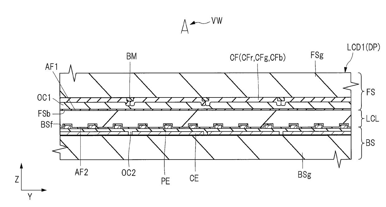
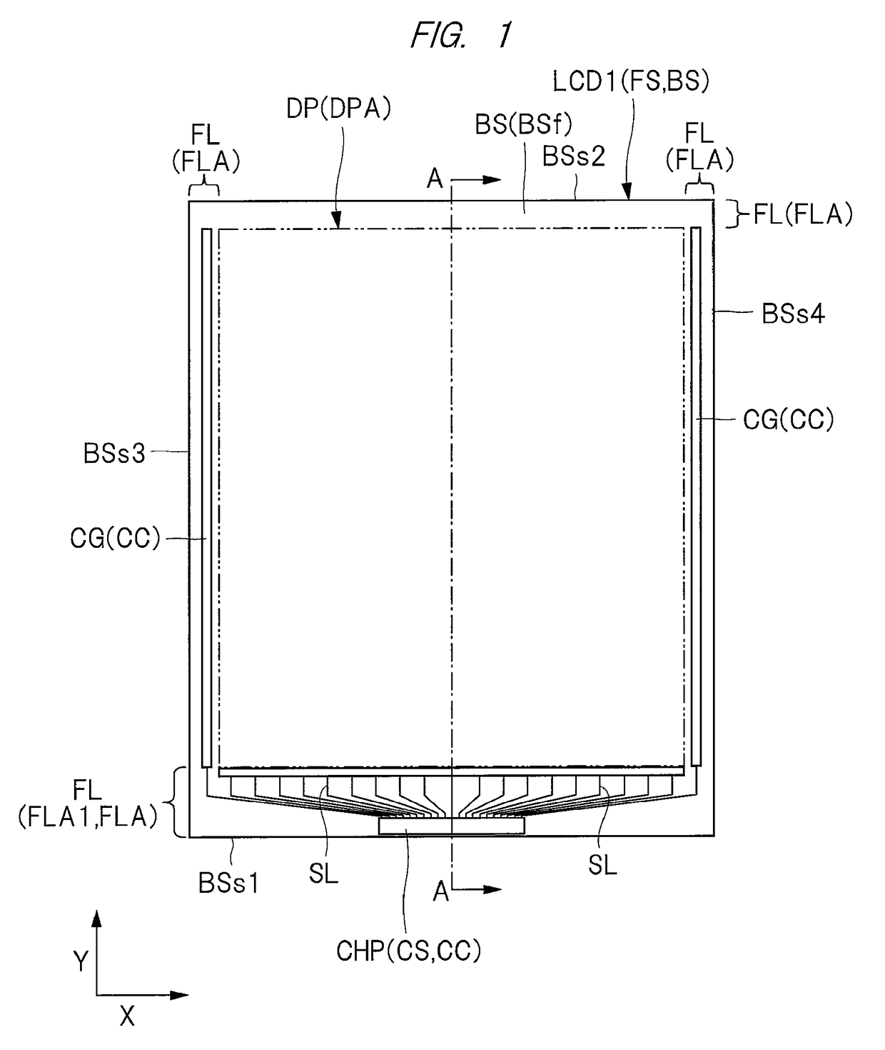
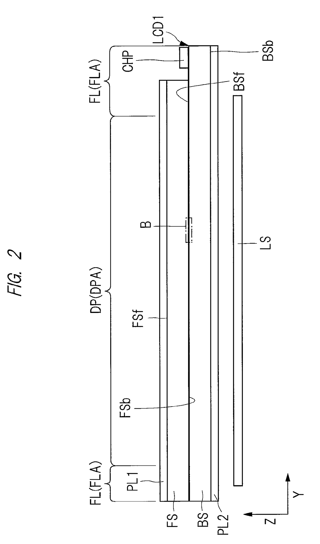
[0044]A configuration of a display device will be first described. FIG. 1 is a plan view illustrating an example of a display device according to an embodiment. FIGS. 2 and 3 are cross-sectional views illustrating the example of the display device according to the embodiment. FIG. 2 is a cross-sectional view taken along a line A-A illustrated in FIG. 1. FIG. 3 is an enlarged sectional view of a portion B illustrated in FIG. 2.

[0045]In FIG. 1, the contour of a display region DPA is indicated by a two-dot and dash line to make a boundary between a display region DPA and a frame region (peripheral area) FLA easy to view in a plan view. A plurality of signal lines SL illustrated in FIG. 1 extend from the frame region FLA to the display region DPA. However, illustration of the signal lines SL is omitted in the display region DPA for ease of viewing in FIG. 1. FIG. 2 illustrates a cross section, where hatching is omitted for ease of viewing.

[0046]As illustra...


PUM

PropertyMeasurementUnit
conductiveaaaaaaaaaa
colorsaaaaaaaaaa
areaaaaaaaaaaa

Abstract

To reduce the area of a portion where a plurality of transistors are provided in a region around a display region and to reduce the area of the region around the display region, a display device includes a first transistor and a second transistor each as a transistor, and the transistor includes a connection wiring that electrically connects a semiconductor film and a source-drain electrode to each other via an opening portion provided in an insulating film. The first transistor and the second transistor are adjacent to each other, and there is a clearance between an end portion, on the side of the second transistor, of the connection wiring in the first transistor and an end portion, on the side of the second transistor, of the opening portion in the first transistor.

Description

CROSS-REFERENCE TO RELATED APPLICATION[0001]The present application claims priority from Japanese Patent Application No. 2015-050405 filed on Mar. 13, 2016, the content of which is hereby incorporated by reference into this application.TECHNICAL FIELD OF THE INVENTION[0002]The present invention relates to a display device, and to technique effectively applied to a display device including a transistor for feeding a signal to a plurality of pixels provided in a display region, for example.BACKGROUND OF THE INVENTION[0003]A display device, which feeds a signal to a plurality of pixels provided in a display region via a plurality of signal lines and displays an image, has been known. In this display device, the area of a region around the display region is required to be reduced to miniaturize the display device and enlarge the display region.[0004]Each of the plurality of pixels includes a plurality of sub-pixels respectively representing colors, i.e., red (R), green (G), and blue (B)...

Claims


Application Information

Patent Timeline
Patent Type & Authority Patents(United States)
IPC IPC(8): G02F1/1343G02F1/1362
CPCG02F1/136286G02F2001/136218G02F1/136218G02F1/134363G02F1/13624G02F1/1368G02F2201/121G09G3/3607
Inventor KOIDE, GENFUKUSHIMA, TOSHIAKI
Owner JAPAN DISPLAY INC
Learn More