System and method for autonomous PTZ tracking of aerial targets
Active Publication Date: 2017-05-16
PURETECH SYST
View PDF5 Cites 19 Cited by
Summary
Abstract
Description
Claims
Application Information
AI Technical Summary
This helps you quickly interpret patents by identifying the three key elements:
Problems solved by technology
Method used
Benefits of technology
Problems solved by technology
Traditionally, such camera networks require a labor-intensive deployment and monitoring by human security personnel.
Human-monitored systems are, in general, relatively costly and prone to human error.
Detecting and tracking an object are not easy tasks, however.
Those functions require powerful video analytics and complex algorithms supporting those analytics.
Object detection is further complicated when the camera imaging the target moves, either because it is mounted to something which is mobile or because the camera is monitoring a wide field of view by a step-and-stare method of camera movement.
Other difficulties exist.
Genera
Method used
Image
Click on the blue label to locate the original text in one second.
Reading with bidirectional positioning of images and text.
Examples
Embodiment Construction
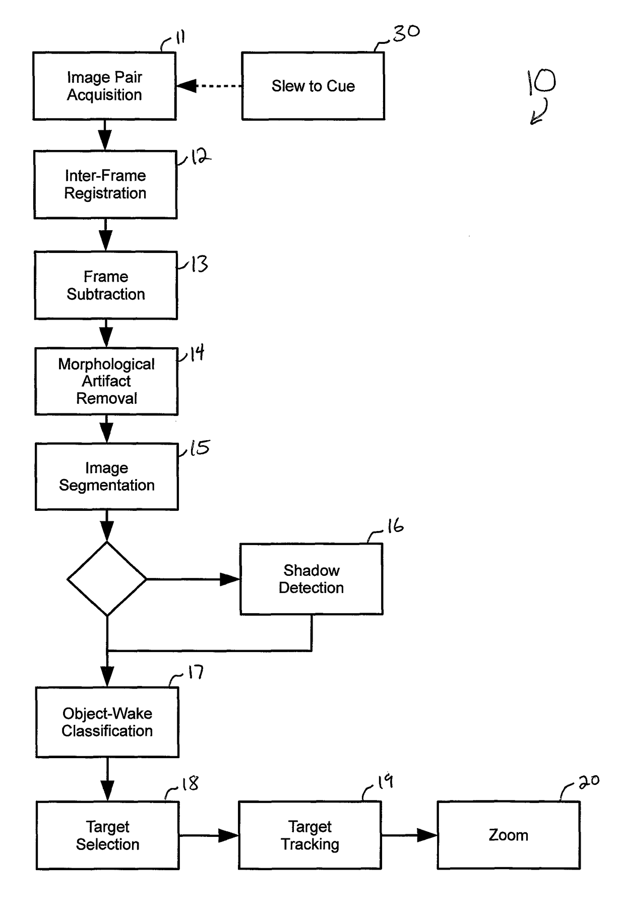
[0021]Reference now is made to the drawings, in which the same reference characters are used throughout the different figures to designate the same elements. FIG. 1 illustrates the principal stages of a process 10 for imaging, analyzing, and tracking an object through terrain space. The process 10 is carried out with a system including an imaging means, such as a PTZ video camera capable of panning, tilting, and zooming through the terrain or real space from a location. In other embodiments, the imaging means is a lidar, radar, sonar, thermal, phase array, ultrasound or sonogram imaging means, or other real imaging means that includes a physical device for capturing information about real space. The various figures, however, illustrate an exemplary imaging means as a PTZ camera. The PTZ camera is mounted to the location but is capable of panning, tilting, and zooming with respect to that mounted location. In a first step 11 of the process, an image pair is acquired.
[0022]In the imag...
PUM
Abstract
A system for autonomous tracking of aerial targets in real space. The imaging means captures and aligns first and second images. A normalized correlation operation initiates a process for producing a resultant image including blobs corresponding to elements in the real space, despite the presence of a homogenous aerial background. One of the blobs is analyzed, classified, and tracked as a target.
Description
CROSS-REFERENCE TO RELATED APPLICATIONS[0001]This application is a continuation-in-part of pending U.S. application Ser. No. 14 / 938,506, filed Nov. 11, 2015, which was a continuation of U.S. application Ser. No. 14 / 569,785, filed Dec. 14, 2014, which was a continuation-in-part of U.S. application Ser. No. 14 / 215,475, filed Mar. 17, 2014, which claimed the benefit of U.S. Provisional Application No. 61 / 793,891, filed Mar. 15, 2013, all of which are hereby incorporated by reference.FIELD OF THE INVENTION[0002]The present invention relates generally to imaging, and more particularly to video surveillance imaging analysis systems and methods.BACKGROUND OF THE INVENTION[0003]The usefulness of video surveillance systems is becoming increasingly acknowledged as the demand for enhanced safety has increased. Areas commonly covered by such systems, include, for example, monitoring of harbors, airports, bridges, power plants, parking garages, public spaces, and other high-value assets. Traditi...
Claims
Application Information
Patent Timeline
Application Date:The date an application was filed.
Publication Date:The date a patent or application was officially published.
First Publication Date:The earliest publication date of a patent with the same application number.
Issue Date:Publication date of the patent grant document.
PCT Entry Date:The Entry date of PCT National Phase.
Estimated Expiry Date:The statutory expiry date of a patent right according to the Patent Law, and it is the longest term of protection that the patent right can achieve without the termination of the patent right due to other reasons(Term extension factor has been taken into account ).
Invalid Date:Actual expiry date is based on effective date or publication date of legal transaction data of invalid patent.

