Image defect inspecting apparatus and image defect inspecting method

a defect inspection and defect technology, applied in image enhancement, instruments, image data processing, etc., can solve problems such as errors and noise, defect inspection cannot be carried out, and the normalized correlation value cannot be calculated by the template imag

Inactive Publication Date: 2007-07-03
FUJIFILM BUSINESS INNOVATION CORP
View PDF4 Cites 14 Cited by
  • Summary
  • Abstract
  • Description
  • Claims
  • Application Information

AI Technical Summary

Benefits of technology

[0020]In the image defect inspecting apparatus according to the invention, the predetermined data patterns are embedded into the same positions of the reference image data and the digital data of the scanned image for inspection by the data embedding unit. Therefore, the normalized correlation coefficient is calculated by the normalized correlation value calculating unit by employing both these image data into which these pattern data have been embedded. As a result, even when such an image data has no change in gray scale values thereof, the gray scale change may occur due to the embedded pattern data, so that the normalized correlation coefficient can be calculated.

Problems solved by technology

Therefore, errors and noise produced from a converting unit for conducting conversion into digital data are mixed into the scanned image for inspection.
In “image matching method and image matching apparatus” disclosed in JP-A-Hei.9-62841, when an image has a low gray scale value (dark image portion) such as a background of an image, the defect inspection based on the normalized correlation value in which a portion having a higher correlation value is forcibly sought owns a problem.
However, there are some cases that the normalized correlation value cannot be calculated by the template image, which is produced from the reference image in view of the defect inspections executed over the entire area of the output image.
In other words, when a defect is present at a position of this portion of the scanned image for inspection, the defect inspection cannot be carried out.
However, this technique owns the following serious drawback.
That is, the higher robustness of the image matching apparatus are lost with respect to the offset variation of the gray scale values of the image and the variation of the illumination light amount, which corresponds to the merit of the defect inspection caused by the normalized correlation of this image matching apparatus.
Also, in the technique disclosed in JP-A-Hei.7-121711, when there is no change in the gray scale values within the template image of the reference image, such a basic problem cannot be solved.
That is, this technique cannot calculate the normalized correlation value.

Method used


Image

  • Image defect inspecting apparatus and image defect inspecting method
  • Image defect inspecting apparatus and image defect inspecting method
  • Image defect inspecting apparatus and image defect inspecting method

Examples


Embodiment Construction

[0030]Referring now to drawings, embodiment modes of the present invention will be described. In this description, the invention is constructed as a part of a print processing system (an image output apparatus) of a laser printer.

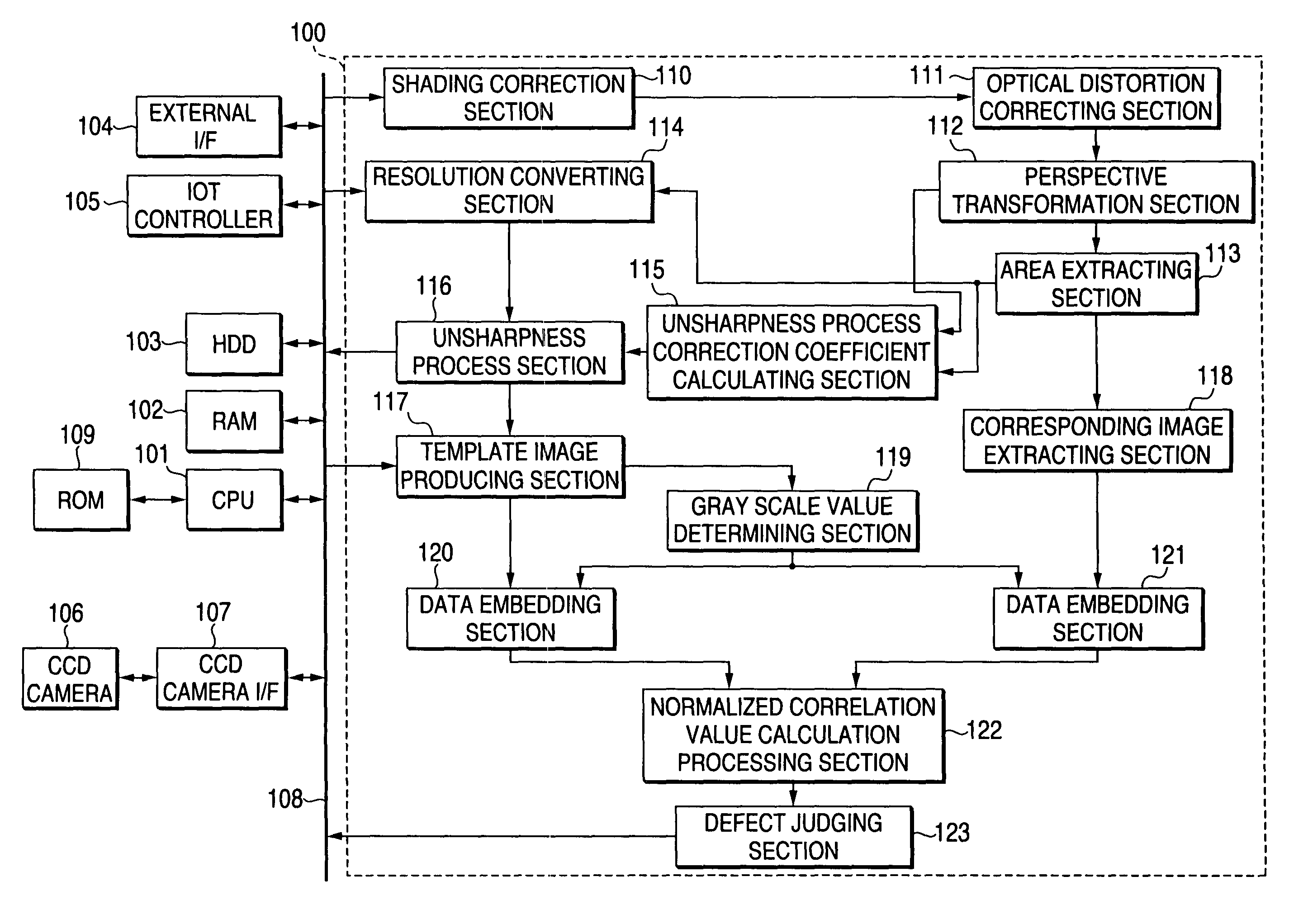
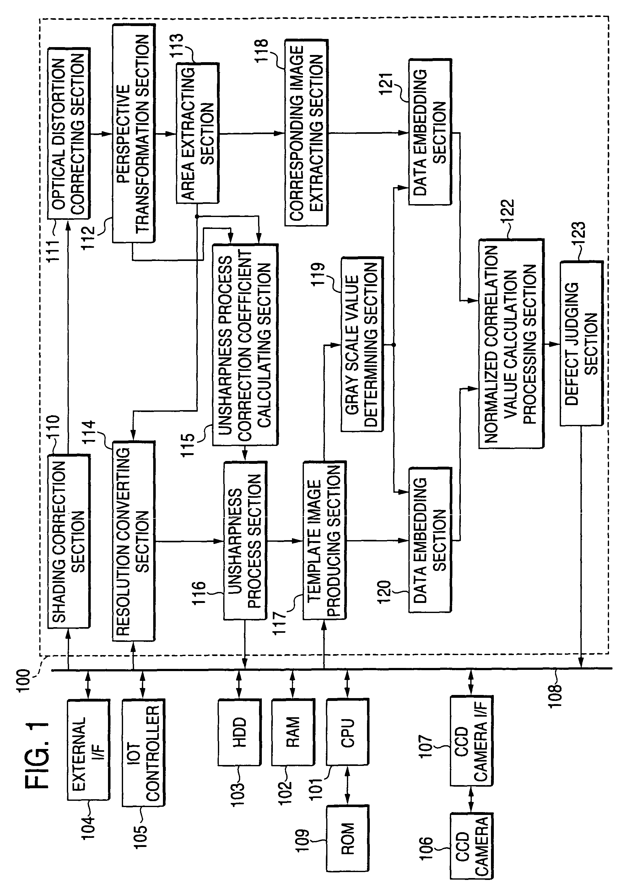
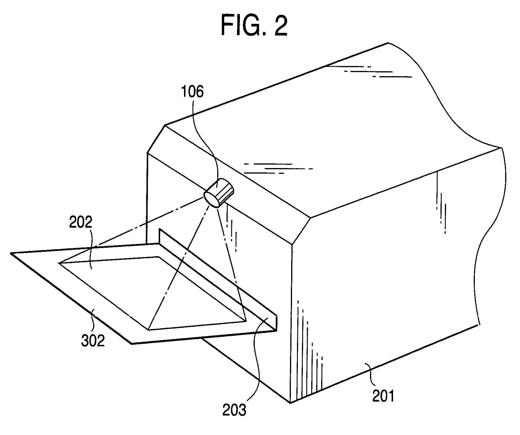
[0031]FIG. 1 is a schematic block diagram for explaining the print processing system to which an image defect inspecting apparatus of the invention is applied. The image defect inspecting apparatus is mounted on a laser printer (will be referred to as a “printer” hereinafter) 201 of FIG. 2.

[0032]As indicated in FIG. 1, in the print processing system, a CPU 101, a RAM 102, a hard disk drive (HDD) 103, an external interface circuit (external I / F) 104, an IOT controller 105 (IOT: image output terminal), and a CCD camera interface 107 for a CCD camera are mutually connected via a data bus 108 to each other. The external I / F 104 is employed so as to input print data from an external. The print data is described in a page description language. The IOT controller ...


PUM

PropertyMeasurementUnit
defectaaaaaaaaaa
sizeaaaaaaaaaa
densityaaaaaaaaaa

Abstract

An image defect inspecting apparatus of the present invention includes a template image producing section for producing a template image from reference image data, a corresponding image extracting section for extracting a predetermined image located at a position corresponding to a template image from digital data of a scanned image for inspection, data embedding sections for embedding desired same pattern data into the template image and the image extracted by the corresponding image extracting section, a normalized correlation value calculation processing unit for acquiring a normalized correlation coefficient from the template image and the extracted image, into which the pattern data is embedded, and a defect judging section for judging as to whether a defect is present by comparing the normalized correlation coefficient acquired by the normalized correlation value calculation processing unit with a predetermined threshold value so as to acquire a large/small relationship thereof.

Description

[0001]The present disclosure relates to the subject matter contained in Japanese Patent Application No.2002-267919 filed on Sep. 13, 2002, which is incorporated herein by reference in its entirety.BACKGROUND OF THE INVENTION[0002]1. Field of the Invention[0003]The present invention relates to an image inspecting apparatus and an image inspecting method, and particularly relates to an image inspecting apparatus employed in an image output apparatus for outputting an image recording medium on which an image has been recorded based upon image data and image inspecting method therefor.[0004]2. Description of the Related Art[0005]Conventionally, as a method of inspecting a defect contained in an output image, a defect inspecting method based upon a normalized correlation method has been proposed. This defect inspecting method owns such a merit that a defect inspection can be carried out in a correct manner even when contrast of a scanned image for inspection is different from that of a r...

Claims


Application Information

Patent Timeline
Patent Type & Authority Patents(United States)
IPC IPC(8): G06K9/00G01N21/88G06F17/15G06F17/18G06T1/00G06T7/00H04N1/00
CPCG06T7/001H04N1/00002H04N1/00015H04N1/00031H04N1/00047H04N1/0005H04N1/00068H04N1/00076H04N1/00079G06T2207/30144
Inventor YASUKAWA, KAORUADACHI, KOJIYAMADA, NORIKAZUNAKAGAWA, EIGOUWATOKO, KOKISATONAGA, TETSUICHI
Owner FUJIFILM BUSINESS INNOVATION CORP
Why Eureka
Try Eureka