Power shutoff device

a technology of power shutoff and connecting member, which is applied in the direction of emergency protection devices, electric switches, electric apparatus, etc., can solve the problems of fuse dropping off from the first housing, further lowering assembly workability, and reducing assembly workability, so as to prevent the drop off of a fuse, improve the assembly workability of the connecting member, and relieve the operation of the attaching/detaching operation of the connecting member

Active Publication Date: 2017-05-16
YAZAKI CORP
View PDF15 Cites 0 Cited by
  • Summary
  • Abstract
  • Description
  • Claims
  • Application Information

AI Technical Summary

Benefits of technology

[0009]The fuse is fixed to the first housing by a bolt which fixes the pair of switch terminals. Thus, when an operator simply tries to mount the fuse to the first housing, for example, after the first housing is assembled to a counterpart mechanism such as an in-vehicle part, the bolt is removed and external terminals connected to the power source side and load side are disposed at the respective input portion and output portion of the fuse, and then it is necessary to fix again, by the bolt, the pair of switch terminals together with the external terminals. For this reason, the number of assembling man hours or the number of parts will be increased, thus causing a possibility of further lowering the assembly workability.
[0023]The embodiment of the present invention brings about an effect of providing a power shutoff device capable of preventing dropping off of a fuse from a box and improving assembly workability.

Problems solved by technology

Thus, after the second housing is dismounted from the first housing, it is necessary to control at least two members, that is, the second housing and the fuse, resulting in lowering of the assembly workability.
For this reason, the number of assembling man hours or the number of parts will be increased, thus causing a possibility of further lowering the assembly workability.
The above structure for locking the fuse by the lock mechanism may cause a possibility that the fuse is unlocked when conveying or assembling the first housing to thereby cause the fuse to drop off from the first housing.

Method used


Image

  • Power shutoff device
  • Power shutoff device
  • Power shutoff device

Examples


Embodiment Construction

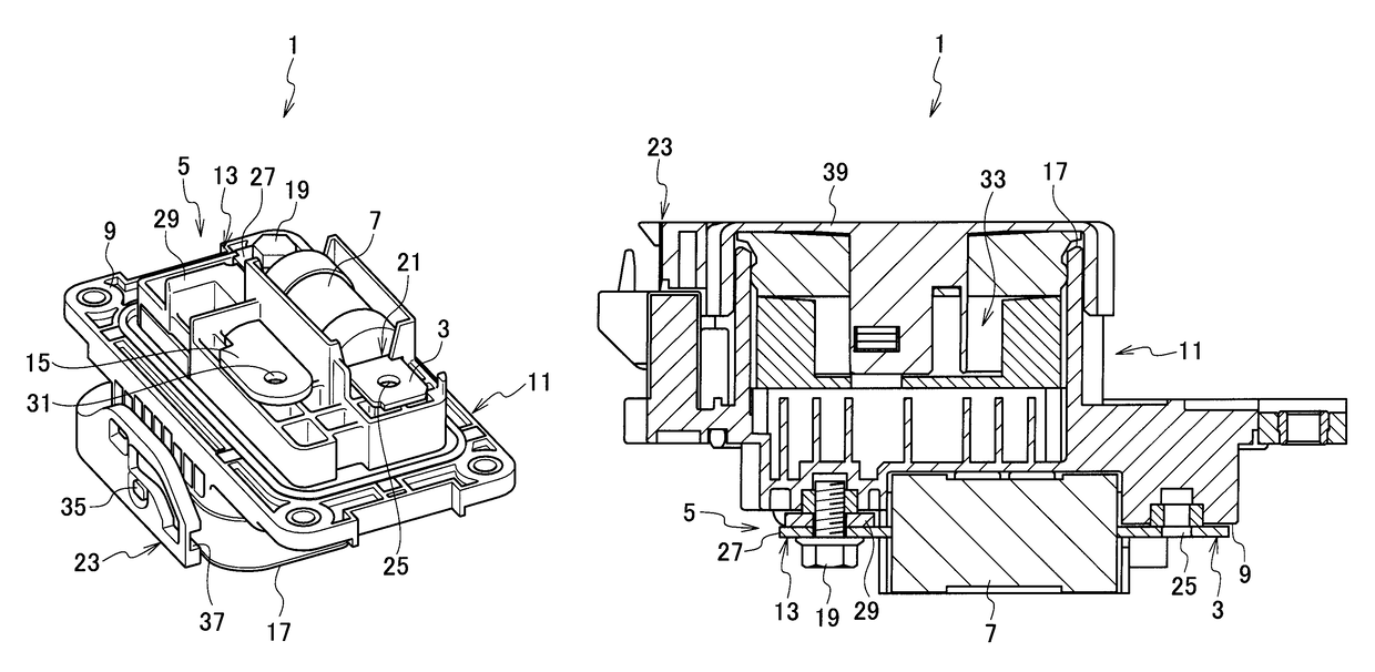
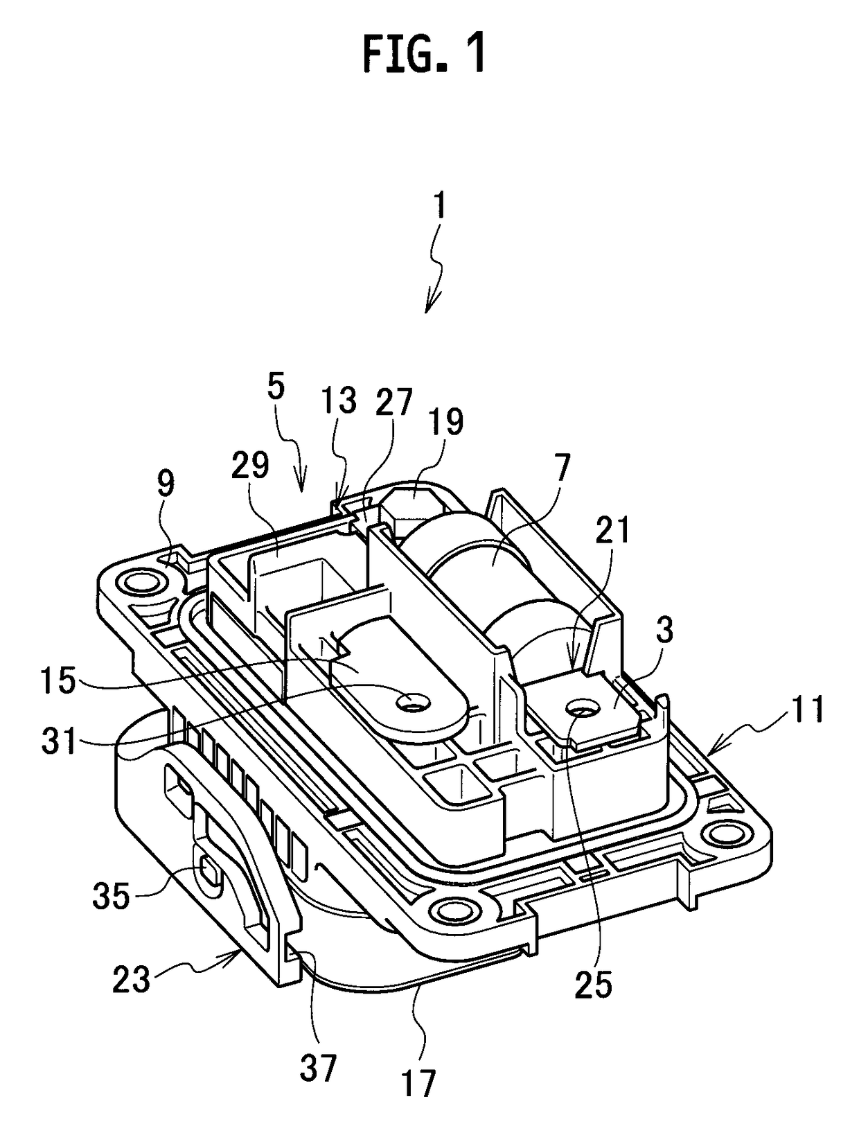
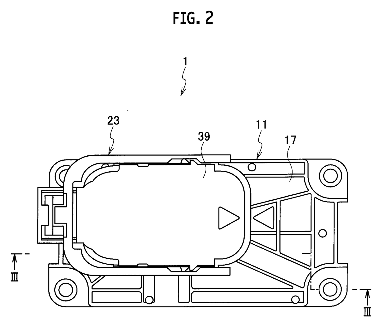
[0029]Referring to FIG. 1 to FIG. 5, a power shutoff device according to an embodiment of the present invention will be set forth.

[0030]A power shutoff device 1 according to the embodiment is provided with an input portion 3 connected to a power source side, an output portion 5 connected to a load side, a fuse 7 disposed between the input portion 3 and the output portion 5 and configured to shut off the conduction between the input portion 3 and the output portion 5 by an overcurrent, and a box 11 having a first face 9 side with the input portion 3, the output portion 5 and the fuse 7 assembled to the first face side.

[0031]The input portion 3 is provided to be integrated with the fuse 7. The output portion 5 includes a first terminal portion 13 provided to be integrated with the fuse 7 and a second terminal portion 15 separated from the fuse 7. The first terminal portion 13 and the second terminal portion 15 are connected with each other via a connecting member (not illustrated) whi...


PUM


Abstract

A power shutoff device includes: a fuse to shut off conduction between the input portion connected to a power source side and the output portion connected to a load side; a box having a first face side with the input portion, the output portion, and the fuse to be assembled thereon; and a lock portion to fix one of the input portion and the output portion to the box. The one of the input portion and the output portion is integrally provided to the fuse. The other of the input portion and the output portion includes a first terminal portion integrally provided to the fuse and fixed to the box via a bolt, and a second terminal portion separately provided from the fuse and connected to the first terminal portion via a connecting member being attachable and detachable on a second face side of the box.

Description

CROSS REFERENCE TO RELATED APPLICATION[0001]This application is based upon and claims the benefit of priority from the prior Japanese Patent Application No. 2011-180252, filed on Aug. 22, 2011, the entire contents of which are incorporated herein by reference.BACKGROUND OF THE INVENTION[0002]1. Field of the Invention[0003]The present invention relates to a power shutoff device disposed between a power source side and a load side.[0004]2. Description of the Related Art[0005]Japanese Patent Unexamined Publication No. 2008-176969 proposes a power shutoff device provided with an input portion connected to a power source side, a pair of switch terminals as an output portion connected to a load side, and a fuse disposed between the pair of switch terminals and capable of shutting the conduction between the pair of switch terminals by an overcurrent.[0006]This power shutoff device is provided with a first housing having a pair of main circuit terminals connected with the pair of switch ter...

Claims


Application Information

Patent Timeline
Patent Type & Authority Patents(United States)
IPC IPC(8): H01H85/50H01H9/08H01H9/10H01H85/20
CPCH01H9/085H01H9/10H01H85/205
Inventor IKEDA, TOMOHIROTAKISHITA, RYUTAMOCHIZUKI, KOUICHIROOHIKE, TERUHIKONOGASHIRA, SHO
Owner YAZAKI CORP
Why Eureka
Try Eureka