Motor with speed reduction mechanism capable of absorbing axial deviation between armature shaft and worm shaft

a technology of axial deviation and speed reduction mechanism, which is applied in the direction of dynamo-electric machines, dynamo-electric components, structural associations, etc., can solve the problems of reduced workability, difficult detection of magnetic detecting elements, and poor accuracy, so as to ensure the workability of assembling the motor with the speed reduction mechanism, the effect of suppressing the increase in manufacturing cost and good accuracy

Active Publication Date: 2012-06-05
MITSUBA CORP
View PDF3 Cites 0 Cited by
  • Summary
  • Abstract
  • Description
  • Claims
  • Application Information

AI Technical Summary

Benefits of technology

[0009]An object of the present invention is to provide a motor with speed reduction mechanism, which can detect a rotation state of a worm wheel side with good accuracy while allowing play between an armature-shaft-side coupling member and a worm-shaft-side coupling member.
[0013]According to the present invention, the other end of the armature shaft is provided together rotatably to the armature-shaft-side coupling member; the one end of the worm shalt is provided together rotatably to the worm-shaft-side coupling member; the armature-shaft-side coupling member and the worm-shaft-side coupling member are coupled together rotatably; and the worm-shaft-side coupling member is provided together rotatably to the sensor magnet. Therefore, the rotation state of the worm shaft can be detected with good accuracy. For this reason, even if play is provided between the armature-shaft-side coupling member and the worm-shaft-side coupling member, this play does not affect the accuracy of detection of the rotation state of the worm shaft, thereby bringing no problem regarding the accuracy of detection of the rotation state of the worm wheel side. Further, since the play can be provided between the armature-shaft-side coupling member and the worm-shaft-side coupling member, workability of assembling the motor with speed reduction mechanism can be ensured, whereby an increase in manufacturing cost can be suppressed.
[0014]According to the present invention, the motor with speed reduction mechanism further includes the connector member provided with the connector connecting portion to which an external connector is connected; the connector member is provided with the sensor substrate that has the magnet sensor for detecting the rotation state of the sensor magnet; the sensor substrate and the connector connecting portion are provided in parallel toward the radial direction of the worm shalt; and the sensor substrate is disposed between the sensor magnet and the connector connecting portion. Therefore, by disposing the magnet sensor near the connector connecting portion, a terminal provided between the magnet sensor and the connector connecting portion can be shortened in length.
[0015]According to the present invention, the connector member is provided integrally with the clipping portion, which is clipped between the yoke and the gear case and overlaps with the brush holder toward the axial direction of the worm shaft; and the sensor substrate is assembled to the clipping portion. Therefore, the magnetic sensor can be provided so as to be spaced apart from the brush, and since electric noise, and abrasion powder, etc. are prevented from reaching the magnetic sensor, a decrease in detection sensitivity of the magnetic sensor can be suppressed.

Problems solved by technology

Therefore, there has been the problem that it is difficult for the magnetic detecting element to detect, with good accuracy, a rotation state of the worm wheel side (such as positional detection of the window glass) due to play between the driving-side rotator and the driven-side rotator.
In this case, however, there arises such a problem as occurrence of necessity for manufacturing the driving-side rotator and the driven-side rotator with good accuracy, and a decrease in workability of assembling the motor with speed reduction mechanism, and the like, as a result of which an increase in manufacturing cost is brought.

Method used


Image

  • Motor with speed reduction mechanism capable of absorbing axial deviation between armature shaft and worm shaft
  • Motor with speed reduction mechanism capable of absorbing axial deviation between armature shaft and worm shaft
  • Motor with speed reduction mechanism capable of absorbing axial deviation between armature shaft and worm shaft

Examples


Embodiment Construction

[0028]An embodiment according to the present invention will be described in detail below with reference to the accompanying drawings.

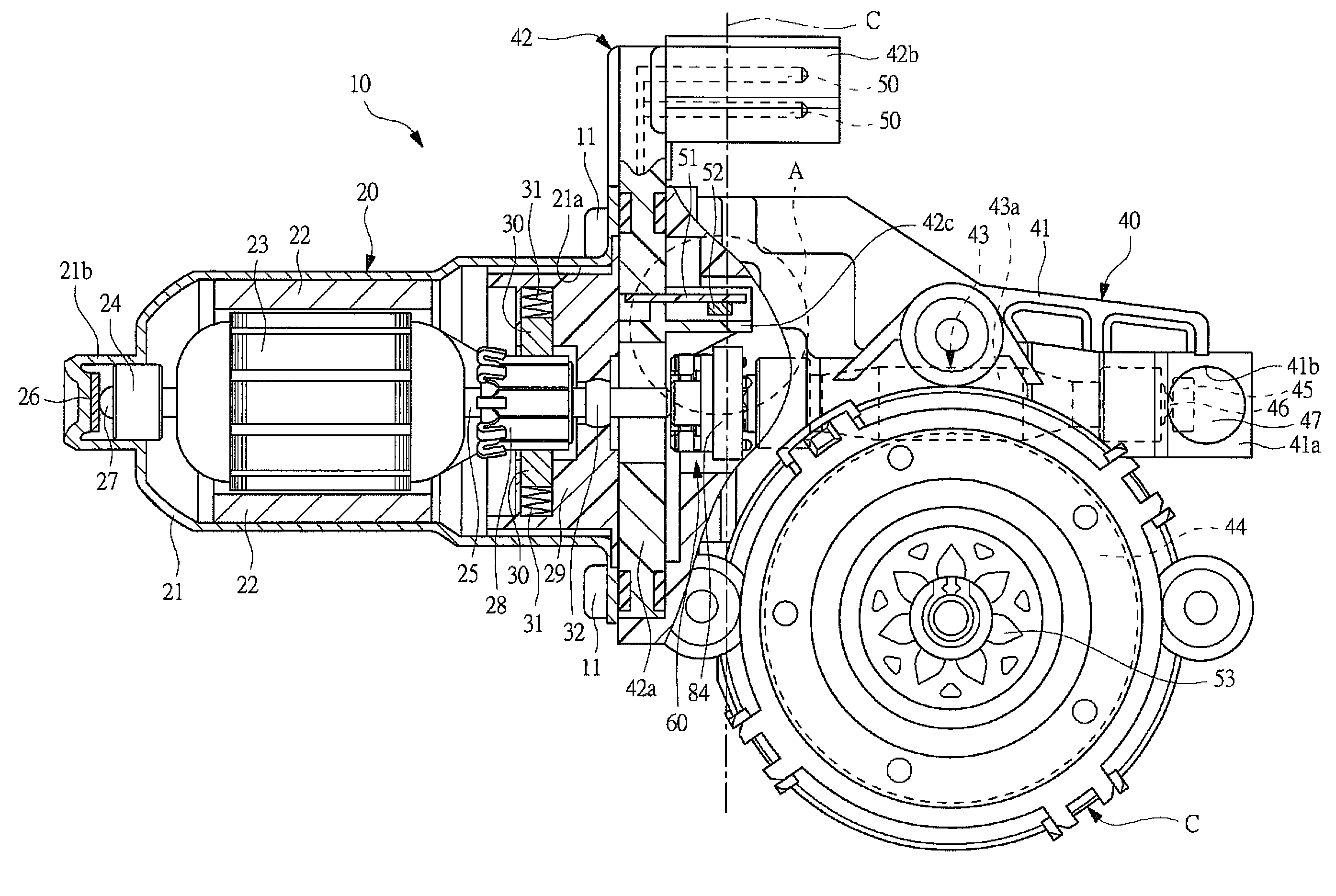
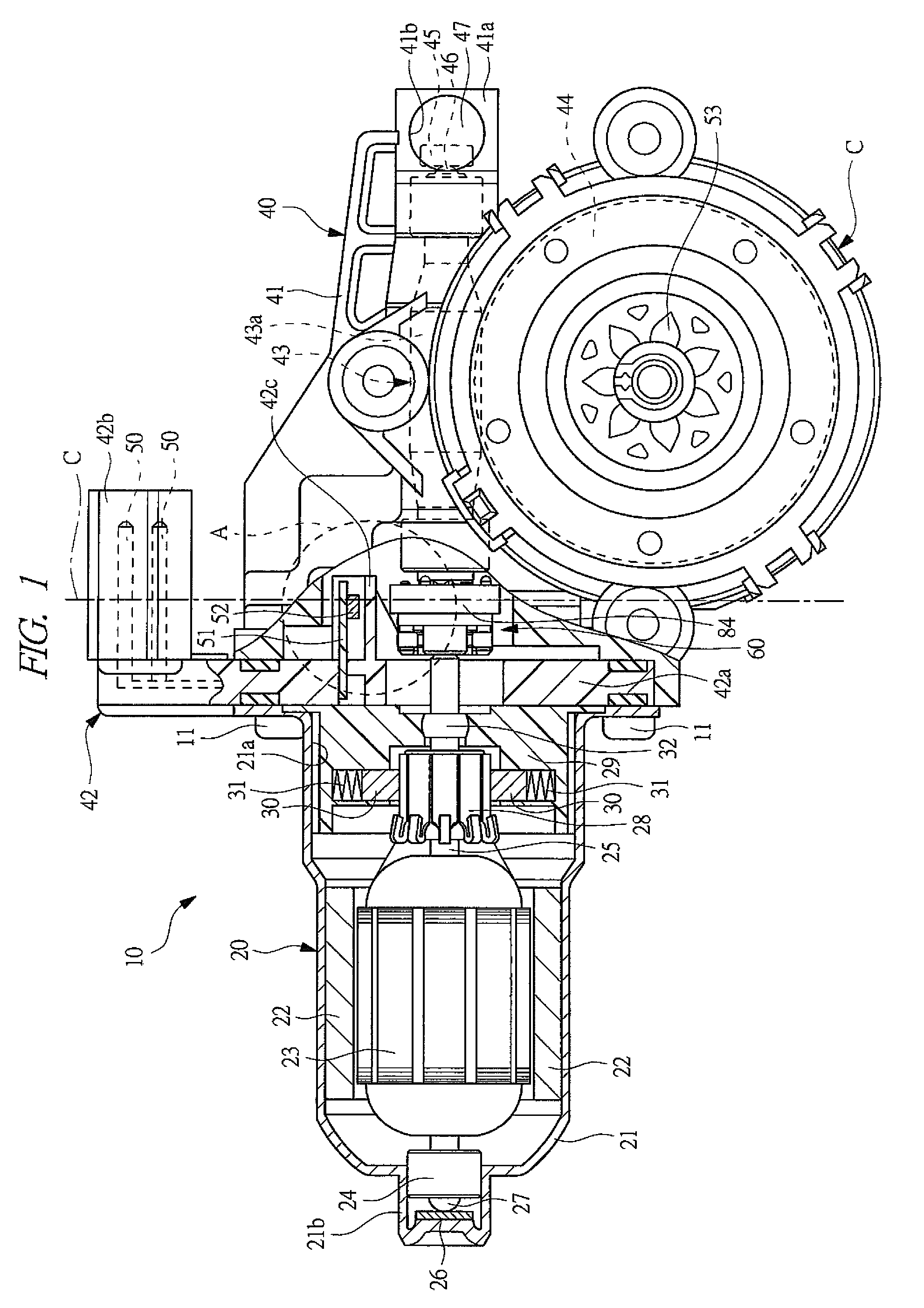
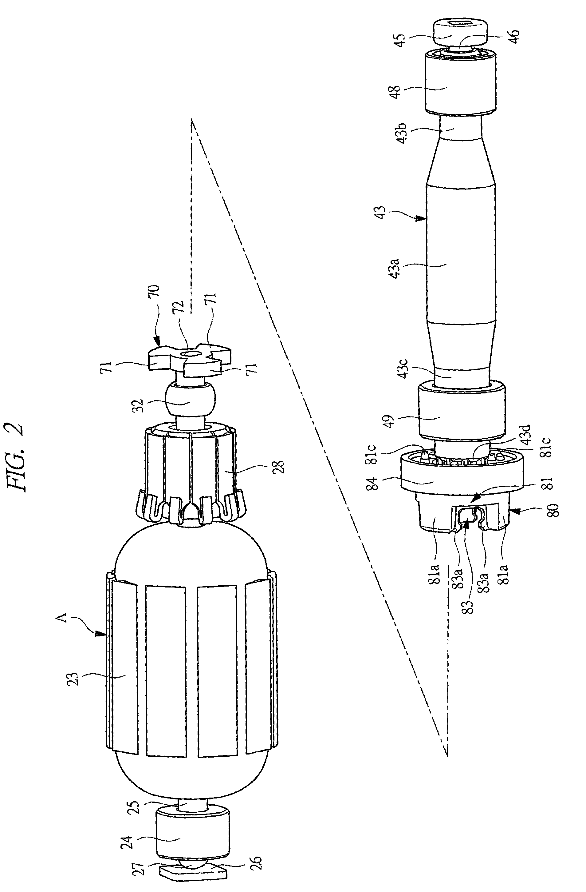
[0029]FIG. 1 represents a partial sectional view of a motor with speed reduction mechanism according to the present invention; FIG. 2 represents a perspective view showing an armature, coupling members, and a worm shaft in the motor with speed reduction mechanism of FIG. 1; FIG. 3 represents an enlarged sectional view for explaining each structure of the coupling members; FIGS. 4A and 4B each represent an explanatory drawing for explaining a procedure for assembling a motor section; FIGS. 5A and 5B each represent an explanatory drawing for explaining a procedure for assembling a gear section; and FIG. 6 represents a perspective view of a connector member viewed from a gear case side.

[0030]As depicted in FIG. 1, a motor with speed reduction mechanism 10 is used as a driving source of a power-window apparatus (not shown) loaded on a vehicle such as an au...


PUM


Abstract

Detecting a rotation state of a worm wheel side with good accuracy while allowing play between an armature-shaft-side coupling member and a worm-shaft-side coupling member. The armature-shaft-side coupling member is provided together rotatably to the other end of an armature shaft; the worm-shaft-side coupling member is provided together rotatably to one end of a worm shaft; the armature-shaft-side coupling member and the worm-shaft-side coupling member are coupled together rotatably; and a sensor magnet is provided together rotatably to the worm-shaft-side coupling member. Therefore, the rotation state of the worm shaft can be detected with good accuracy. Even if the play is provided between the armature-shaft-side coupling member and the worm-shaft-side coupling member, this play does not affect the accuracy of detection of the rotation state of the worm shaft, thereby bringing no problem regarding accuracy of detection of a rotation state of a worm wheel side.

Description

CROSS-REFERENCE TO RELATED APPLICATION[0001]Applicant hereby claims foreign priority benefits under U.S.C. §119 from Japanese Patent Application No. 2008-331166 filed on Dec. 25, 2008, the contents of which are incorporated by reference herein.TECHNICAL FIELD OF THE INVENTION[0002]The present invention relates to a motor with speed reduction mechanism, which has a gear section decelerating rotation of a motor section.BACKGROUND OF THE INVENTION[0003]Conventionally, used as a driving source for a power-window apparatus, sun-roof apparatus, or the like loaded on a vehicle such as an automobile is a motor with speed reduction mechanism, which can produce a large output although small in size. This motor with speed reduction mechanism is driven by rotation when an operation switch provided in a vehicle compartment or the like is operated by an operator, thereby driving an open / close body (such as a window glass or sun roof) for opening and closing.[0004]Since an on-vehicle motor with sp...

Claims


Application Information

Patent Timeline
Patent Type & Authority Patents(United States)
IPC IPC(8): H02K23/66H02K7/10
CPCH02K7/1166H02K5/143H02K11/0021H02K11/215
Inventor UCHIMURA, HIROYUKISHIBUSAWA, HIROYUKIMITA, MASAKI
Owner MITSUBA CORP
Why Eureka
Try Eureka