Power transmitting apparatus

a technology of power transmission and transmission device, which is applied in mechanical devices, transportation and packaging, gearing, etc., can solve the problems and achieve the effect of reducing the workability of assembly of driving devices

Active Publication Date: 2010-07-20
FCC KK
View PDF11 Cites 0 Cited by
  • Summary
  • Abstract
  • Description
  • Claims
  • Application Information

AI Technical Summary

Benefits of technology

[0012]An aspect of at least one of the embodiments disclose herein includes the realization that there is a problem in the power transmitting apparatus of the prior art that it is difficult to align the tip end of the driving shaft with the “D” shaped aperture of the stay when anchoring the stay to the tip end of the driving shaft. That is, since the through aperture of the stay cannot be watched by a worker with it being interrupted by the substrate, the rotational member or the connecting member integrated with the driving shaft, the tip end of the driving shaft has been anchored to the trough aperture of the stay with taking aim gropingly (by “feel”). This has extremely reduced the workability of assembly of the driving device.

Problems solved by technology

This has extremely reduced the workability of assembly of the driving device.

Method used


Image

  • Power transmitting apparatus
  • Power transmitting apparatus
  • Power transmitting apparatus

Examples


Embodiment Construction

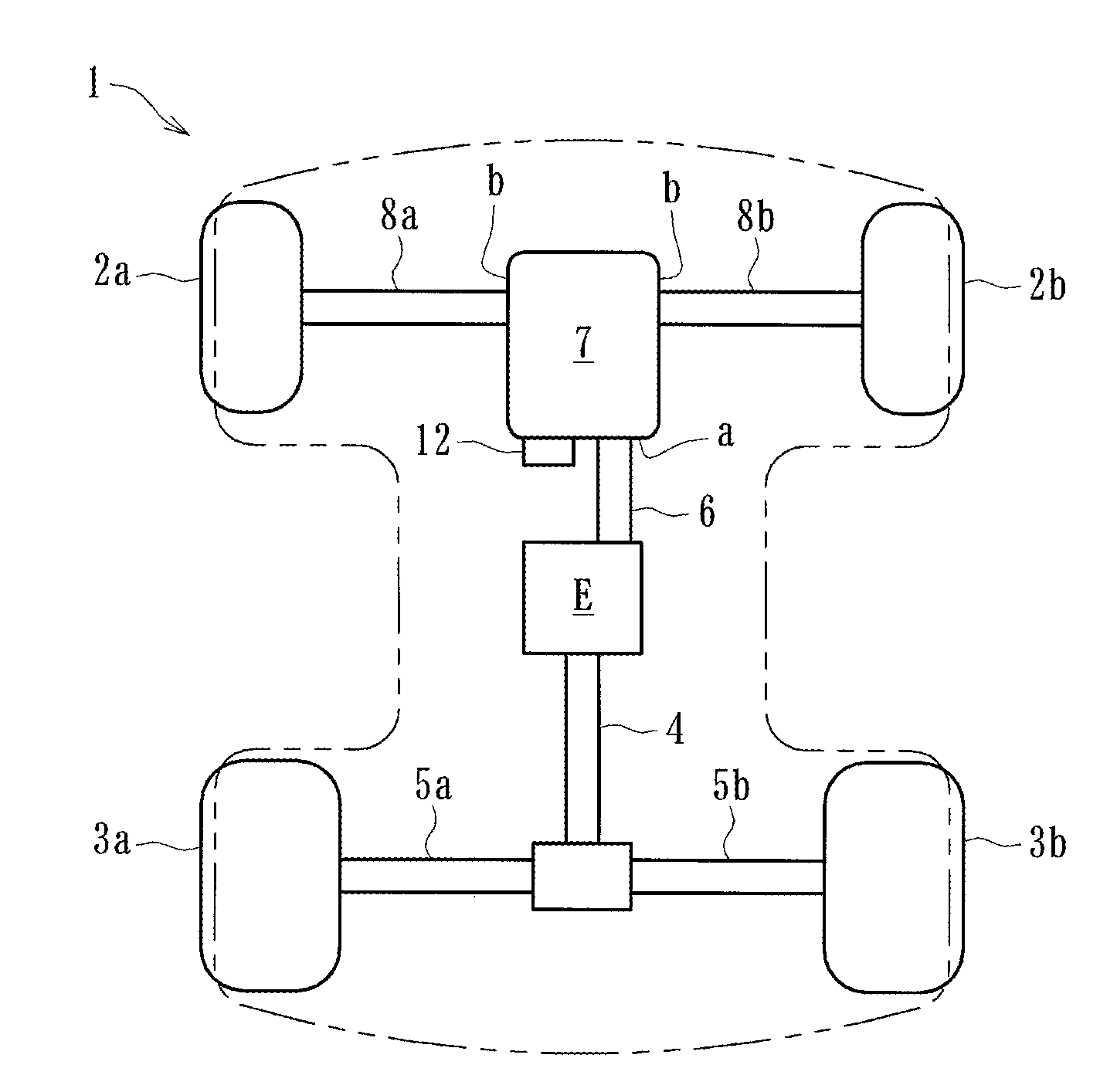
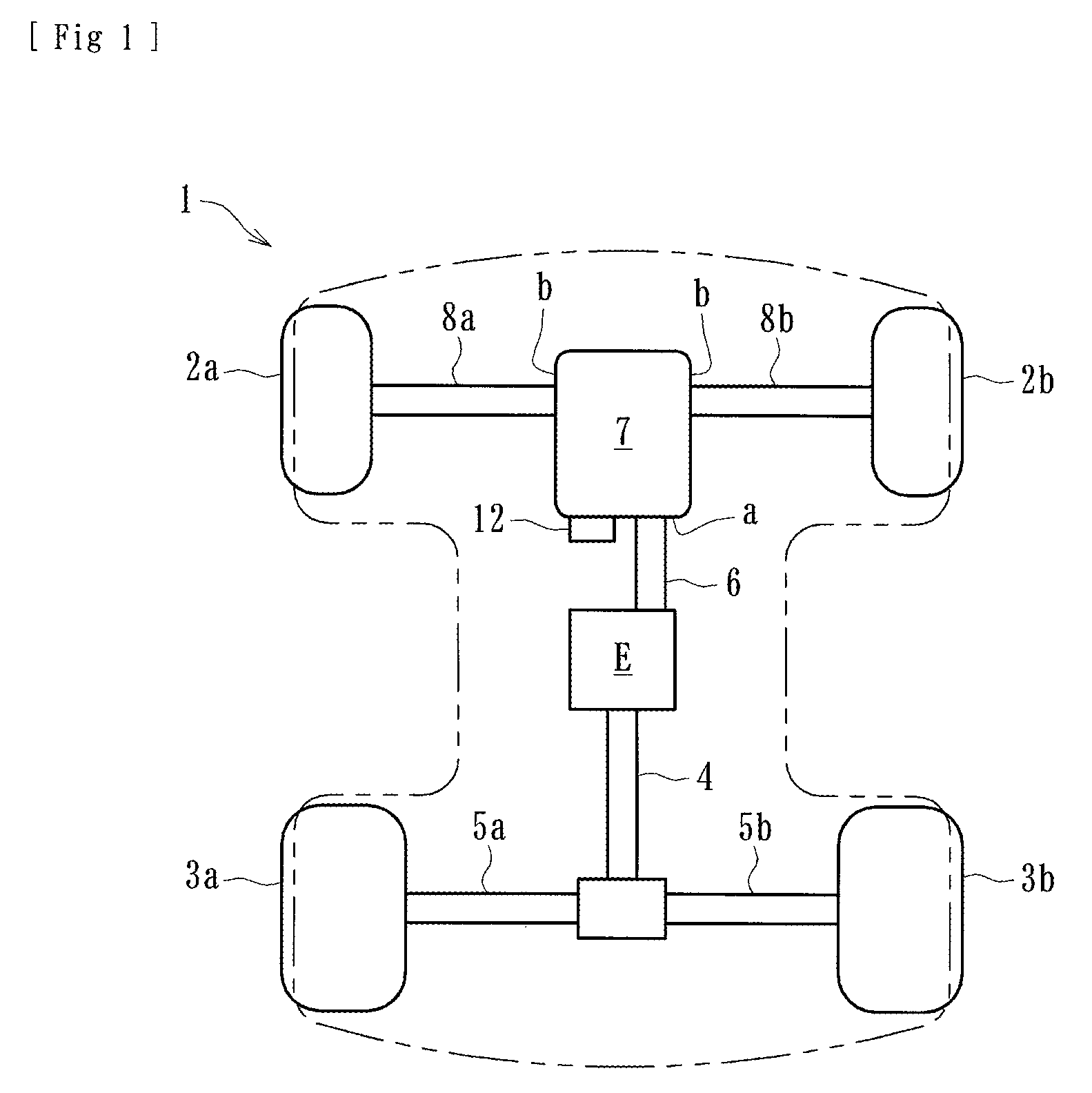
[0029]As shown in FIG. 1 a power transmitting apparatus cane be mounted between front wheels 2a and 2b in a front region of a vehicle such as a 4-wheel buggy or an ATV (All Terrain Vehicle) for performing the switching between 2-wheel and 4-wheel drive modes as well as locking and unlocking of a differential device. The power transmitting apparatus is disclosed in the context of an ATV because it has particular utility in this context. However, the power transmitting apparatus can be used in other contexts, such as, for example, but without limitation, other vehicles including land vehicles.

[0030]As shown in FIG. 1 a propulsion shaft 4 extends from an engine (driving power source) “E” toward the rear of a vehicle to drive rear wheels 3a and 3b respectively via driving shafts 5a and 5b. Another propulsion shaft 6 (input shaft) also extends from the engine “E” and is connected to the power transmitting apparatus 7. These propulsion shafts 4 and 6 are connected to the engine “E” to be ...


PUM


Abstract

A power transmitting apparatus for performing switching between 2-wheel and 4-wheel drive modes and locking and unlocking of differential mechanism by an operational shaft can include a driving device comprising a reversible motor, a rotational member rotationally driven by the motor and provided with a contacting member. A spring can be arranged on the rotational member, a connecting member can be arranged to be abutted by one end of the spring so as to be rotated by the rotational member via the coil spring, and a driving shaft can be rotatably arranged relative to the rotational member and engaged by the operational shaft in its rotational direction and adapted to be rotated by the rotational member via the connecting member. A stay can be engaged by the driving shaft in its rotational direction and provided with a contacting member. A substrate can be arranged so as to be contacted by the contacting members respectively of the rotational member and the stay and formed with a conducting patterns forming predetermined electric circuits in accordance with the rotational angles respectively of the rotational member and the driving shaft. The rotational member, connecting member, stay and substrate can be formed as separate parts and adapted to be assembled to the driving shaft in order.

Description

PRIORITY INFORMATION[0001]This application is based on and claims priority under 35 U.S.C. §119 to Japanese Patent Application No. 2007-127167, filed on May 11, 2007, the entire contents of which is hereby expressly incorporated by reference herein.BACKGROUND OF THE INVENTIONS[0002]1. Field of the Inventions[0003]The present inventions relate to power transmitting apparatuses for switching between 2-wheel and 4-wheel modes and locking and unlocking differential devices.[0004]2. Description of the Related Art[0005]Four-wheel buggies, also known as “ATVs” (All Terrain Vehicles), usually include power transmitting apparatuses for connecting and disconnecting power from an engine to the front wheels, which are not-driven wheels, and also switching between 2-wheel and 4-wheel drive modes. Such a vehicle is disclosed in Japanese Laid-open Patent Publication No. 191768 / 2003.[0006]Generally, the power transmitting apparatus is provided with a differential mechanism (differential gear set) t...

Claims


Application Information

Patent Timeline
Patent Type & Authority Patents(United States)
IPC IPC(8): F16H48/06B60K23/08F16H48/08F16H48/24F16H48/30F16H48/34F16H48/38
CPCB60K17/354B60W10/119B60W10/16B60W30/18F16H63/304Y10T477/613F16H2063/3056F16H2063/3066F16H59/70
Inventor CHIBA, RYOUHEIMIWA, NAOYUKI
Owner FCC KK
Why Eureka
Try Eureka