Power shutoff device

Active Publication Date: 2013-02-28
YAZAKI CORP
View PDF8 Cites 2 Cited by
  • Summary
  • Abstract
  • Description
  • Claims
  • Application Information

AI Technical Summary

Benefits of technology

[0022]According to the above structure, the connecting member is attached to the box or detached from the box via the lever. Thus, it is possible to relieve an attaching/detaching operational force of the connecting member, thus making it possible to improve

Problems solved by technology

Thus, after the second housing is dismounted from the first housing, it is necessary to control at least two members, that is, the second housing and the fuse, resulting in lowering of the assembly workability.
For this reason, the number of assembling man hours or the number of parts will be incre

Method used


Image

  • Power shutoff device
  • Power shutoff device
  • Power shutoff device

Examples


Embodiment Construction

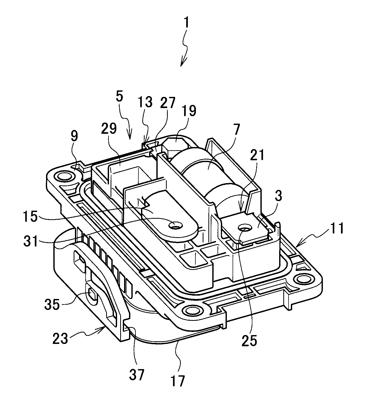
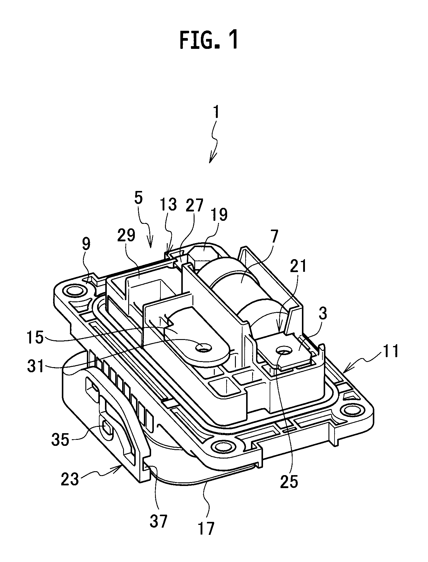
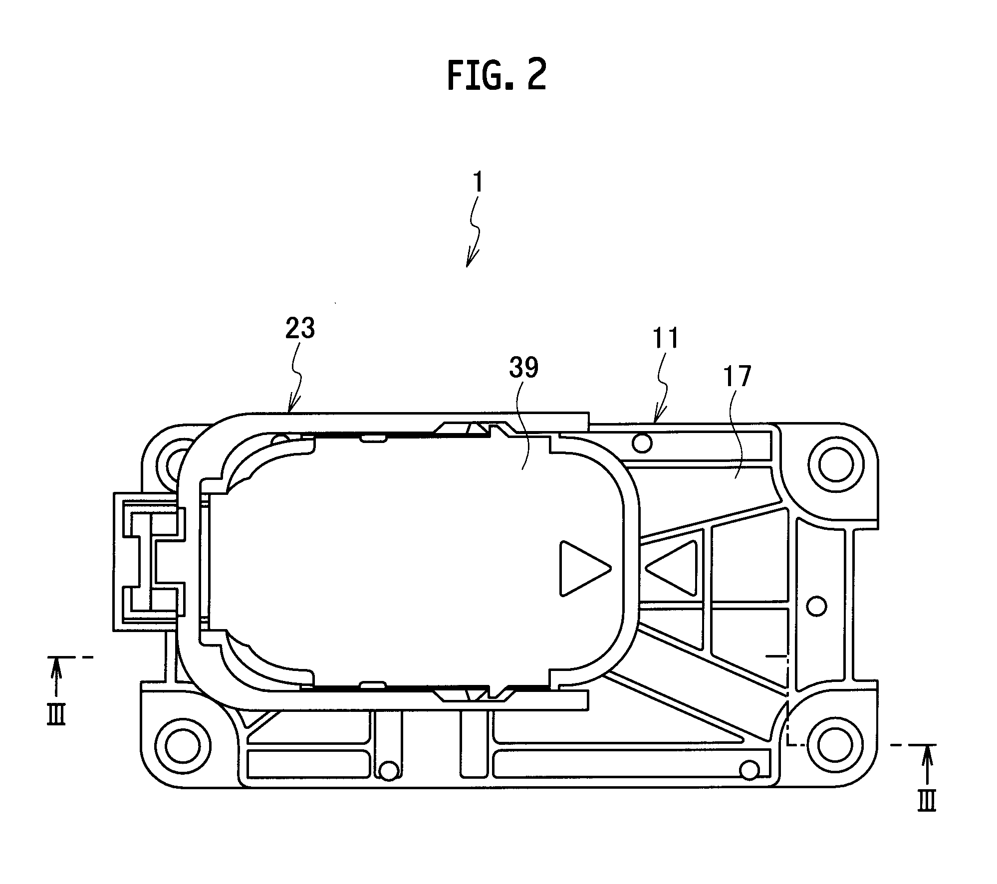
[0029]Referring to FIG. 1 to FIG. 5, a power shutoff device according to an embodiment of the present invention will be set forth.

[0030]A power shutoff device 1 according to the embodiment is provided with an input portion 3 connected to a power source side, an output portion 5 connected to a load side, a fuse 7 disposed between the input portion 3 and the output portion 5 and configured to shut off the conduction between the input portion 3 and the output portion 5 by an overcurrent, and a box 11 having a first face 9 side with the input portion 3, the output portion 5 and the fuse 7 assembled to the first face side.

[0031]The input portion 3 is provided to be integrated with the fuse 7. The output portion 5 includes a first terminal portion 13 provided to be integrated with the fuse 7 and a second terminal portion 15 separated from the fuse 7. The first terminal portion 13 and the second terminal portion 15 are connected with each other via a connecting member (not illustrated) whi...


PUM


Abstract

A power shutoff device includes: a fuse to shut off conduction between the input potion connected to a power source side and the output portion connected to a load side; a box having a first face side with the input portion, the output portion, and the fuse to be assembled thereon; and a lock portion to fix one of the input portion and the output portion to the box. The one of the input portion and the output portion is integrally provided to the fuse. The other of the input portion and the output portion includes a first terminal portion integrally provided to the fuse and fixed to the box via a bolt, and a second terminal portion separately provided from the fuse and connected to the first terminal portion via a connecting member being attachable and detachable on a second face side of the box.

Description

CROSS REFERENCE TO RELATED APPLICATION[0001]This application is based upon and claims the benefit of priority from the prior Japanese Patent Application No. 2011-180252, filed on Aug. 22, 2011, the entire contents of which are incorporated herein by reference.BACKGROUND OF THE INVENTION[0002]1. Field of the Invention[0003]The present invention relates to a power shutoff device disposed between a power source side and a load side.[0004]2. Description of the Related Art[0005]Japanese Patent Unexamined Publication No. 2008-176969 proposes a power shutoff device provided with an input portion connected to a power source side, a pair of switch terminals as an output portion connected to a load side, and a fuse disposed between the pair of switch terminals and capable of shutting the conduction between the pair of switch terminals by an overcurrent.[0006]This power shutoff device is provided with a first housing having a pair of main circuit terminals connected with the pair of switch ter...

Claims


Application Information

Patent Timeline
IPC IPC(8): H01H85/50
CPCH01H9/085H01H85/205H01H9/10
Inventor IKEDA, TOMOHIROTAKISHITA, RYUTAMOCHIZUKI, KOUICHIROOHIKE, TERUHIKONOGASHIRA, SHO
Owner YAZAKI CORP
Why Eureka
Try Eureka