Chip substrate comprising a groove portion and chip package using the chip substrate

a chip substrate and groove technology, applied in the field of chip substrates, can solve problems such as reducing the reliability of chip packages, and achieve the effects of enhancing the reliability of lens bonding, preventing adhesive agents, and preventing adhesive agents

Active Publication Date: 2017-05-16
POINT ENG
View PDF11 Cites 0 Cited by
  • Summary
  • Abstract
  • Description
  • Claims
  • Application Information

AI Technical Summary

Benefits of technology

[0007]In view of the above technical problem, it is an object of the present invention to provide a chip substrate structure capable of preventing an adhesive agent from being exposed to the light emitted from optical elements by forming a groove portion.
[0008]More specifically, it is an object of the present invention to provide a chip substrate and a lens structure, which are capable of preventing an adhesive agent from being exposed to the light emitted from optical elements by forming a groove portion to which the adhesive agent can be applied.
[0021]According to the present invention, an adhesive agent is applied in a groove portion formed in advance. It is therefore possible to prevent the adhesive agent from being exposed to the light emitted from optical elements and to prevent the adhesive agent from being denatured. This makes it possible to enhance the reliability of lens bonding. Furthermore, there is no need to use an expensive resistant adhesive agent. An existing typical adhesive agent may be used as it is. This provides an effect of saving costs. Thus, there is an advantage in that a low-priced existing bonding material may be applied to a high-priced UV-C (deep-UV) package.

Problems solved by technology

Since the adhesive agent has no resistance to the light, there is a problem in that the adhesive agent is denatured or hardened over time, thereby reducing the reliability of a chip package.

Method used


Image

  • Chip substrate comprising a groove portion and chip package using the chip substrate
  • Chip substrate comprising a groove portion and chip package using the chip substrate
  • Chip substrate comprising a groove portion and chip package using the chip substrate

Examples


Embodiment Construction

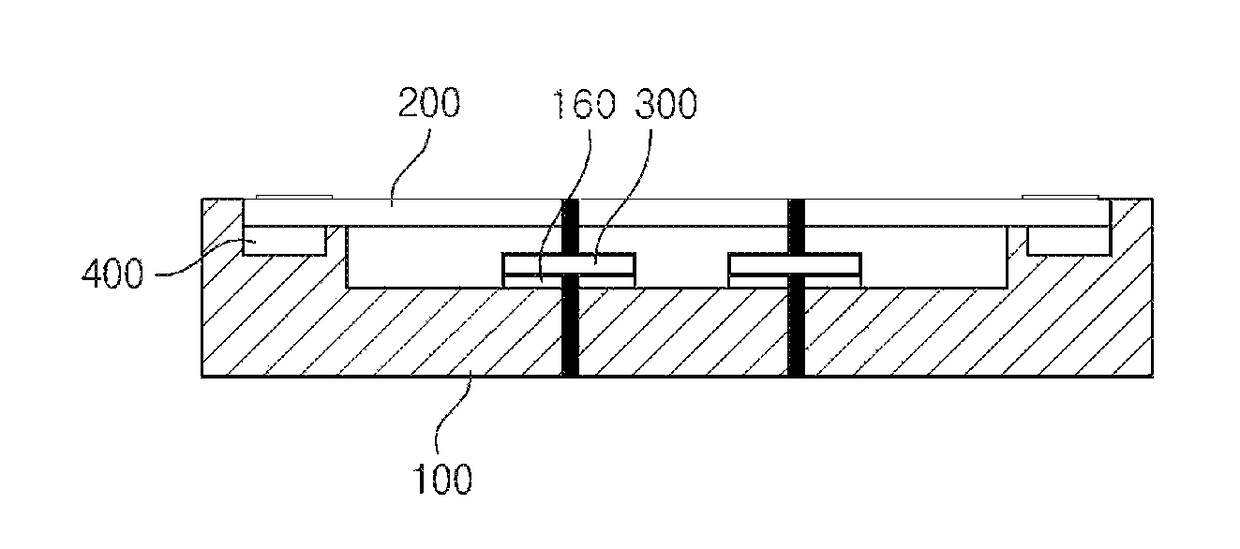
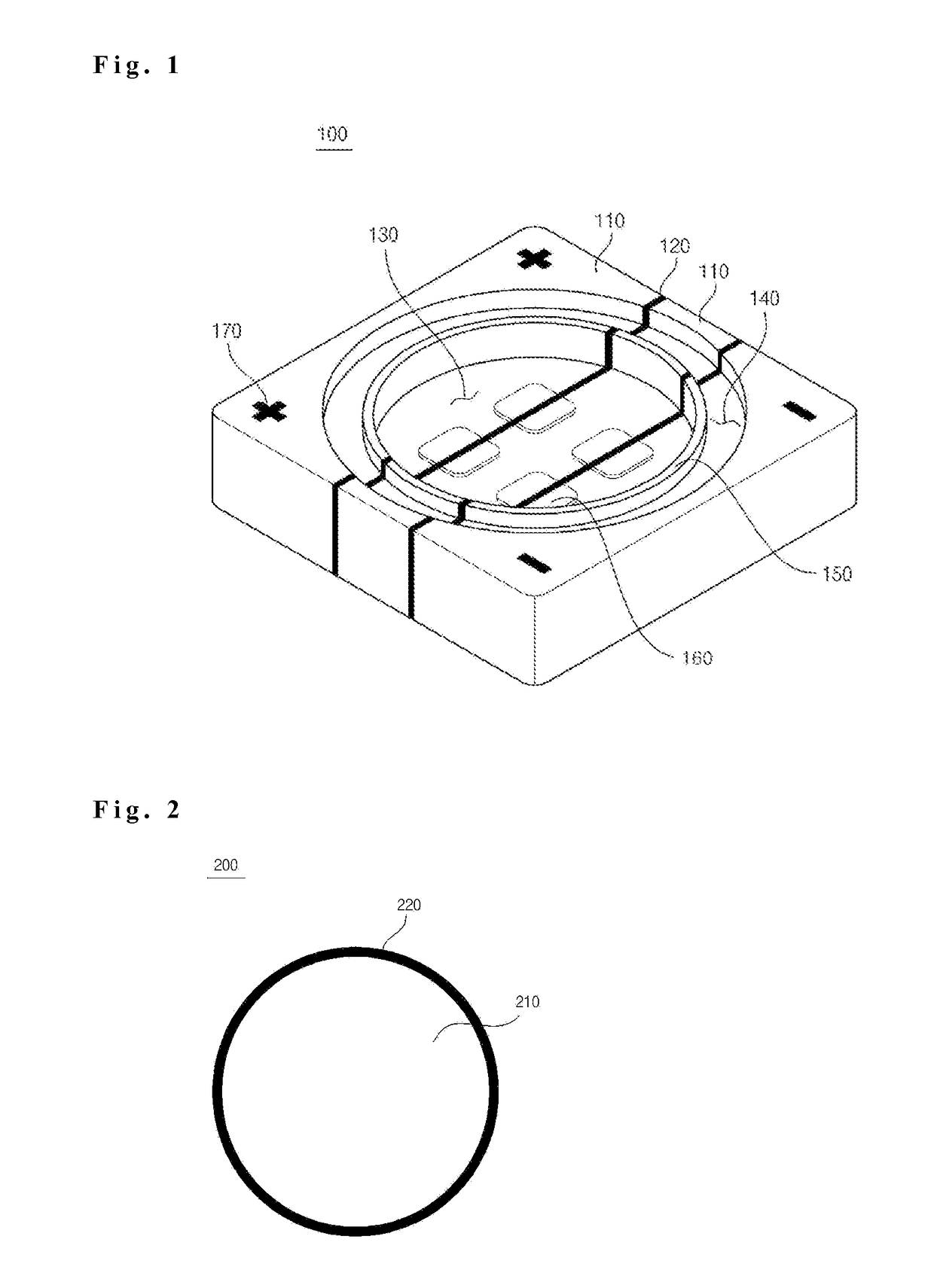
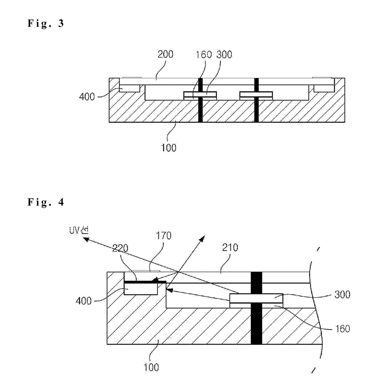
[0026]The following disclosure merely illustrates the principle of the invention. While not explicitly described or illustrated in the subject specification, it may be possible to invent different devices which realize the principle of the invention and which fall within the conception and scope of the invention. Furthermore, all the conditional terms and embodiments disclosed herein are essentially intended to facilitate understanding of the concept of the invention. It is to be understood that the embodiments and states specifically described herein are not limitative.

[0027]The above objects, features and advantages will become more apparent from the following detailed descriptions given in conjunction with the accompanying drawings. Thus, a person having an ordinary knowledge in the technical field to which the invention pertains will be able to easily carry out the technical concept of the invention.

[0028]In describing the invention, if it is determined that the detailed descrip...


PUM


Abstract

Disclosed is a chip substrate. The chip substrate includes: conductive portions laminated in one direction to constitute the chip substrate; insulation portions alternately laminated with the conductive portions to electrically isolate the conductive portions; a cavity formed at a predetermined depth in a recessed shape in a region including the insulation portions on an upper surface of the chip substrate; and a groove portion disposed outside the cavity in a spaced-apart relationship with the cavity and formed at a predetermined depth in a recessed shape. According to the present invention, an adhesive agent is applied in a groove portion formed in advance. It is therefore possible to prevent the adhesive agent from being exposed to the light emitted from optical elements and to prevent the adhesive agent from being denatured. This makes it possible to enhance the reliability of lens bonding. Furthermore, there is no need to use an expensive resistant adhesive agent. An existing typical adhesive agent may be used as it is. This provides an effect of saving costs. Thus, there is an advantage in that a low-priced existing bonding material may be applied to a high-priced UV-C (deep-UV) package.

Description

BACKGROUND[0001]1. Technical Field[0002]The present invention relates to a chip substrate and, more particularly, to a chip substrate including a groove portion and a chip package using the same.[0003]2. Description of Related Art[0004]In the related art, spaces for mounting chips to an uncut chip plate are formed on the upper surface of the uncut chip plate by mechanical processing or chemical etching. That is to say, Korean Patent No. 10-0986211 discloses a method in which mounting spaces are formed by etching an upper portion of an unprocessed rectangular uncut metal plate.[0005]In the case where optical element chips such as UV LEDs or the like are mounted on such an uncut chip plate, spaces having a wide-top / narrow-bottom shape are formed in the uncut chip plate in order to enhance the light reflection performance. A chip package is manufactured by mounting chips in the spaces thus formed and sealing the spaces with molded lenses.[0006]In this case, an adhesive agent (silicon, ...

Claims


Application Information

Patent Timeline
Patent Type & Authority Patents(United States)
IPC IPC(8): H01L29/22H01L33/58H01L33/48H01L33/62H05K1/03H05K1/02
CPCH01L33/58H01L33/486H01L33/62H05K1/0274H05K1/0313H05K2201/2054H01L33/44
Inventor HAN, SIN SEOKCHOI, SOO YOUNGNAM, KI MYUNG
Owner POINT ENG
Why Eureka
Try Eureka