Light-deprivation system

a technology of light-deprived greenhouses and greenhouses, applied in the field of light-deprived greenhouses, can solve the problems of accelerating the wear and tear rate of shades and related components, difficult and expensive maintenance and repair, and high manufacturing and assembly costs of light-deprived greenhouses

Active Publication Date: 2021-09-28
NYDEGGER TRENT R
View PDF23 Cites 0 Cited by
  • Summary
  • Abstract
  • Description
  • Claims
  • Application Information

AI Technical Summary

Benefits of technology

[0007]In an embodiment, a light-deprivation system is in the general shape of a pyramid. Four roller shades form a perimeter around a growing area. A vertical pole is located in the center of the growing area, extending to a pinnacle of the light-deprivation system. The free end of each roller shade is attached to the first end of a line. Each line runs from the free end of the respective shade to the top of the pole. The second end of each line is attached to a reel located on the pole. When activated, the reel reels in each line to draw each shade. The reel also has a release. Engaging the release of the reel allows the roller shades to retract and roll-up into a storage position at the perimeter of the growing area, thereby opening each shade to expose the growing area to natural light.
[0009]A vertical pole is located in the center of the greenhouse, extending substantially to the pinnacle of the light-deprivation system. The free end of each roller shade is attached to the first end a line. Each line runs from the free end of the respective shade along the respective wall to the top of the pole. The second end of each line is attached to a reel. When activated, the reel reels in each line to draw each shade. The reel also has a release. Engaging the release of the reel allows the roller shades to retract and roll-up into a storage position at the base of each wall, thereby opening each shade.
[0010]In another embodiment, a track is located along the joint of each wall and runs substantially along the length thereof. The side edges of each shade engage with the track when the shade is drawn. The tracks support the edges of the shades to help prevent the edges of the shades from drooping when the shades are drawn to prevent light from entering the greenhouse. The tracks may also engage the sides of the shades in a manner that helps to prevent light from entering the greenhouse at the seams between shades.

Problems solved by technology

However, these and other conventional light-deprivation greenhouses employ complex systems, complex motors, and numerous components, all of which contribute to make such light-deprivation greenhouses expensive to manufacture and assemble.
Additionally, the complex machinery and components of such light-deprivation greenhouses are prone to wear, malfunction, and failure, making them difficult and expensive to maintain and repair.
This placement exposes the shades to the elements, thereby accelerating the rate at which the shades and related componentry wear down and malfunction.

Method used


Image

  • Light-deprivation system
  • Light-deprivation system
  • Light-deprivation system

Examples


Embodiment Construction

[0016]Several embodiments of the present disclosure will be described below.

[0017]In an effort to provide a concise description of these embodiments, some features of an actual embodiment may be described in the specification. It should be appreciated that in practice, as in any engineering or design project, numerous embodiment-specific decisions will be necessary to achieve the developers' specific goals, such as compliance with system-related and business-related constraints, which may vary from one embodiment to another. It should further be appreciated that such a development effort might be complex and time consuming, but would nevertheless be a routine undertaking of design, fabrication, and manufacture for those of ordinary skill having the benefit of this disclosure.

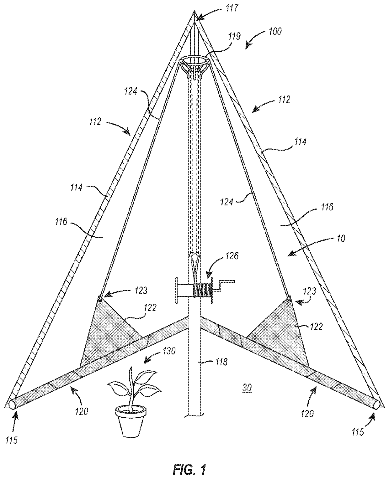
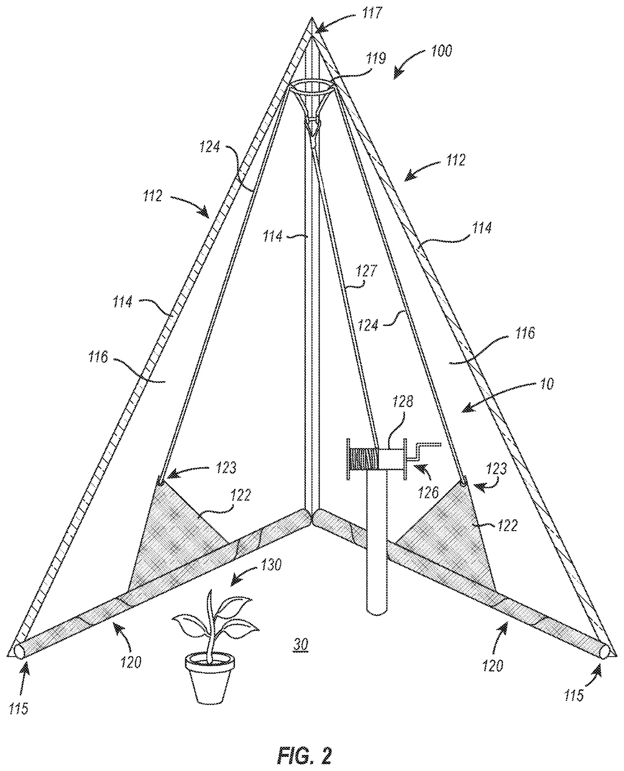
[0018]FIGS. 1 and 2 depict a cross-section of two embodiments of a light-deprivation system installed in a greenhouse 100 according to the present disclosure. While this embodiment of a light-deprivation system ...


PUM


Abstract

A light-deprivation system includes shades having a fixed end that form a perimeter that defines a growing environment, cables attached to a free end of each shade, a cable guide located near a pinnacle of the light-deprivation system, and a winch to draw the shades. The cables run from the free end of each shade, through the cable guide, to the winch. Operation of the winch draws the shades simultaneously to block substantially all light from sources external to the growing environment from reaching the growing environment.

Description

BACKGROUND OF THE DISCLOSURE[0001]Plants need various periods of exposure to light and periods of darkness when the plants are deprived of light to maximize their growth potential and yield. Various greenhouses have been developed with shades to control the periods of time to which plants are provided with and deprived of light. Such greenhouses are commonly referred to as light-deprivation greenhouses.[0002]Examples of various conventional light-deprivation greenhouses are disclosed in U.S. Patent Application Publication No. 2014 / 0157662 to Wallace et al., U.S. Pat. No. 4,064,648 to Cary, U.S. Patent Application Publication No. 2004 / 0134122 to Van Bergen-Henegouwen et al., and U.S. Pat. No. 5,802,762 to Stonecypher.[0003]However, these and other conventional light-deprivation greenhouses employ complex systems, complex motors, and numerous components, all of which contribute to make such light-deprivation greenhouses expensive to manufacture and assemble. The light deprivation syst...

Claims


Application Information

Patent Timeline
Patent Type & Authority Patents(United States)
IPC IPC(8): A01G13/02A01G9/22
CPCA01G13/0206A01G9/227E04F10/06Y02A40/25
Inventor NYDEGGER, TRENT R.
Owner NYDEGGER TRENT R
Why Eureka
Try Eureka