Wearable resistance garment with power measurement
What is AI technical title?
AI technical title is built by Patsnap AI team. It summarizes the technical point description of the patent document.
a resistance garment and power measurement technology, applied in the field of wearable resistance garments with power measurement, can solve the problems of many types of exercise equipment, such as free weights and most exercise machines, not being portable, and many types of exercise equipment, such as resistance bands, to achieve the effect of improving the wearability and the wearability of the garmen
Active Publication Date: 2017-05-23
TAU ORTHOPEDICS LLC
View PDF207 Cites 9 Cited by
Summary
Abstract
Description
Claims
Application Information
AI Technical Summary
This helps you quickly interpret patents by identifying the three key elements:
Problems solved by technology
Method used
Benefits of technology
Problems solved by technology
Various limitations exist with the prior art exercise devices.
For example, many types of exercise equipment, such as free weights and most exercise machines, are not portable.
With respect to exercise bands and tubing, they may need to be attached to a stationary object, such as a closed door or a heavy piece of furniture, and require sufficient space.
This becomes a problem when, for example, the user wishes to perform resistance exercises in a location where such stationary objects or sufficient space are not readily found.
Resistance bands are also limited to a single resistance profile in which the amount of resistance changes as a function of angular displacement of the joint under load.
This may result in under working the muscles at the front end of a motion cycle, and over working the muscles at the back end of the cycle.
Conventional elastic devices also provide a unidirectional bias that varies in intensity throughout an angular range but not in direction.
Such devices thus cannot work both the flexor and extensor muscles of a given motion segment without adjustment, and may be uncomfortable due to the constant bias even in the absence of motion.
Method used
Image
Click on the blue label to locate the original text in one second.
Reading with bidirectional positioning of images and text.
Examples
Embodiment Construction
[0059]Detailed descriptions of the preferred embodiments are provided herein. It is to be understood, however, that the present invention may be embodied in various other forms. Therefore, specific details disclosed herein are not to be interpreted as limiting, but rather as a basis for the claims and as a representative basis for teaching one skilled in the art to employ the present invention in virtually any appropriately detailed system, structure or manner.
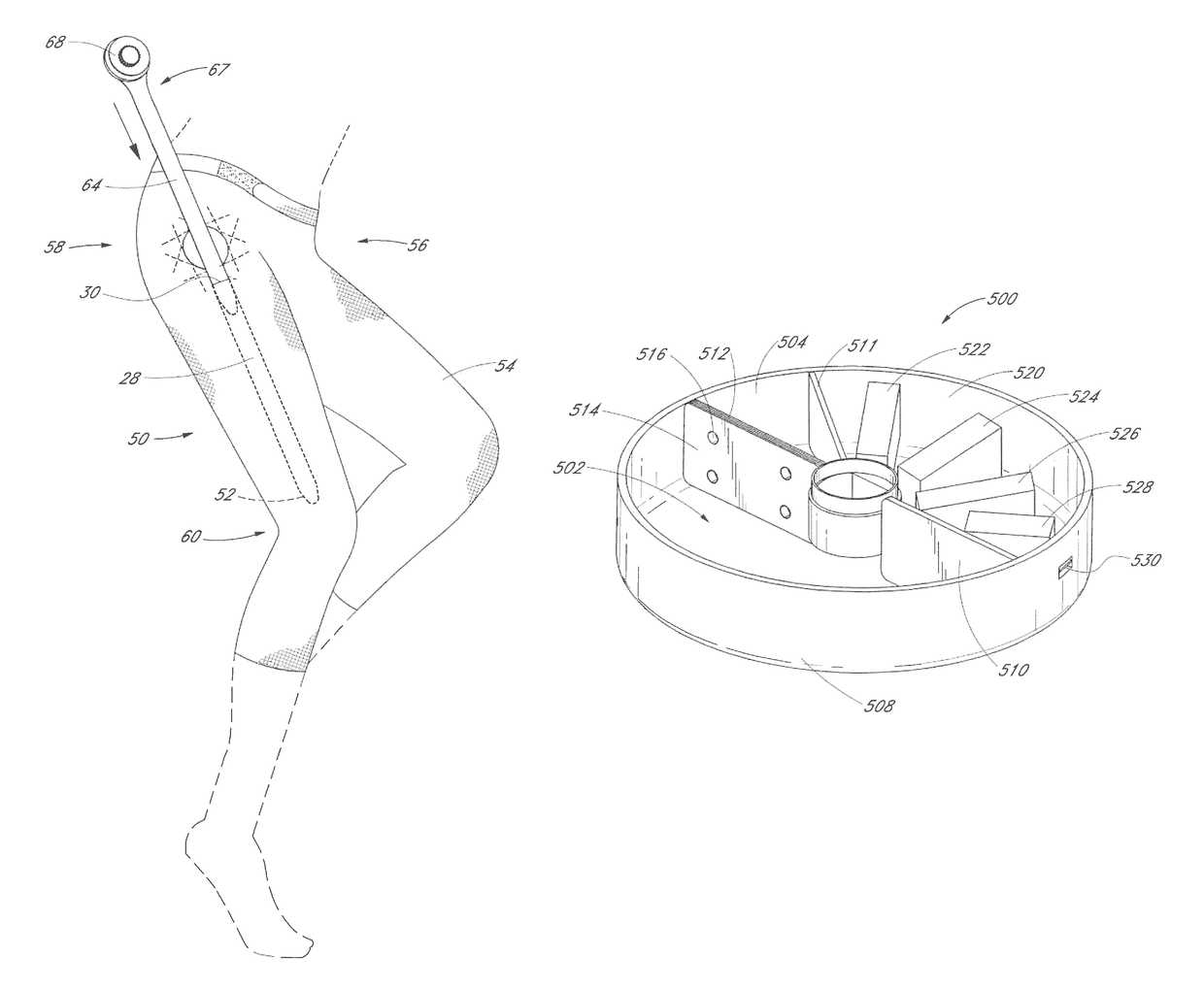
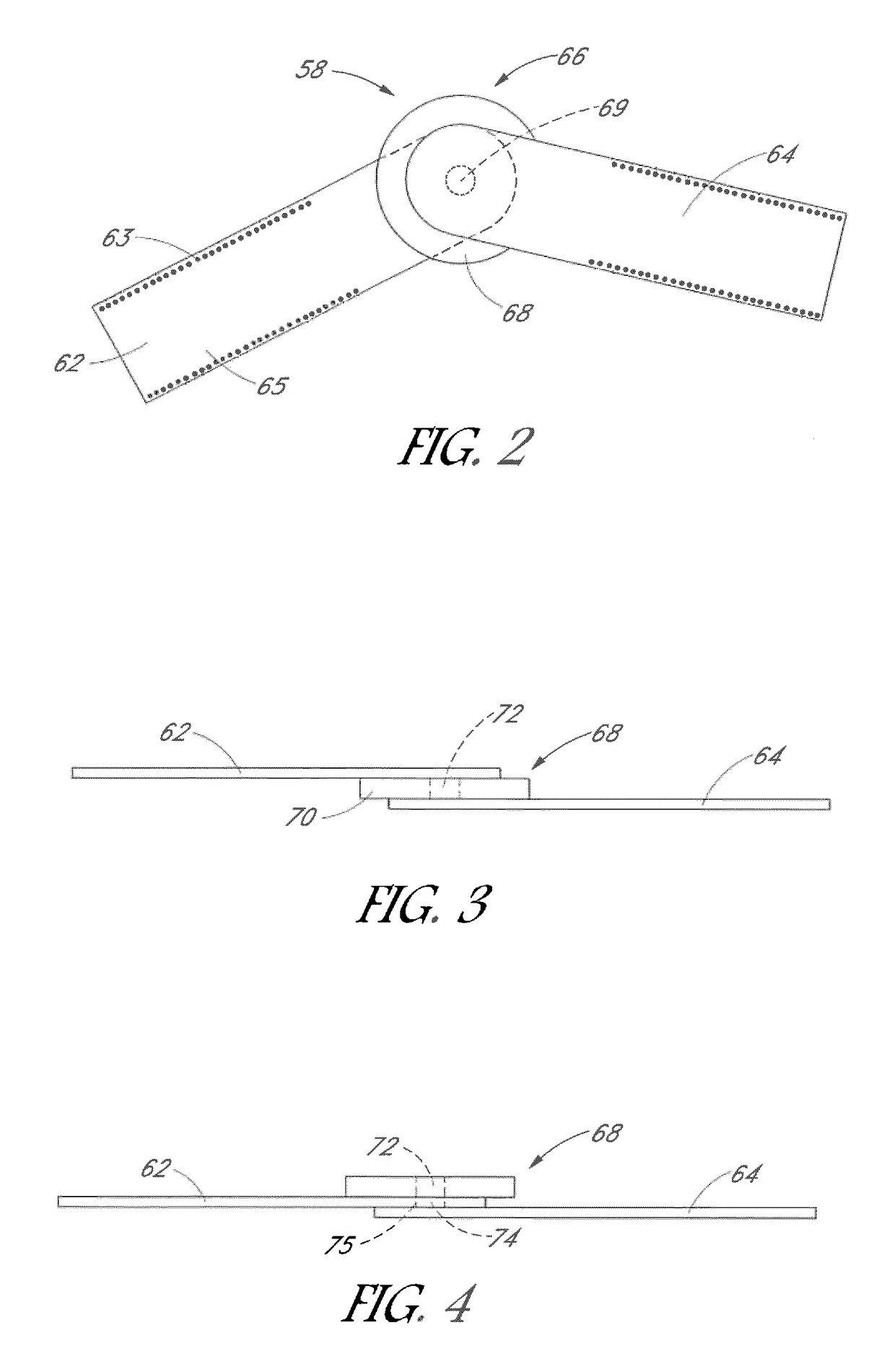
[0060]In general, the devices in accordance with the present invention are designed to provide resistance to motion between a first region and a second region of the body such as across a simple or complex joint, (e.g., hip, knee, shoulder, elbow, etc.), throughout an angular range of motion. The resistance can be either unidirectional, to isolate a single muscle or muscle group, or preferably bidirectional to exercise opposing muscle pairs or muscle groups. Optionally, the device will be user adjustable or interchangeable to ...
PUM
Abstract
Disclosed is a technical training garment configured for use with modular, interchangeable electronics and resistance modules. The garment provides resistance to movement throughout an angular range of motion and tracks biomechanical parameters such as stride length, stride rate, angular velocity and incremental power expended by the wearer. The garment may be low profile, and worn by a wearer as a primary garment or beneath or over conventional clothing. Alternatively, the device may be worn as a supplemental training tool during conventional training protocols.
Description
CROSS-REFERENCE TO RELATED APPLICATIONS[0001]This application is a continuation-in-part of U.S. patent application Ser. No. 15 / 069,053, filed Mar. 14, 2016. This application is also a continuation-in-part of U.S. patent application Ser. No. 14 / 665,947, filed Mar. 23, 2015, which is a continuation-in-part of U.S. patent application Ser. No. 12 / 951,947, filed on Nov. 22, 2010, now U.S. Pat. No. 8,986,177, which is a continuation-in-part of U.S. patent application Ser. No. 12 / 797,718, filed on Jun. 10, 2010 which claims the benefit of U.S. Provisional Application No. 61 / 218,607, filed Jun. 19, 2009. U.S. patent application Ser. No. 14 / 665,947, filed Mar. 23, 2015 is also a continuation-in-part of U.S. patent application Ser. No. 14 / 450,228 filed Aug. 2, 2014, which is a continuation in part of U.S. patent application Ser. No. 14 / 217,576 filed Mar. 18, 2014, which is a continuation in part of U.S. patent application Ser. No. 14 / 192,805 filed Feb. 27, 2014. This application also claims t...
Claims
Application Information
Patent Timeline
Application Date:The date an application was filed.
Publication Date:The date a patent or application was officially published.
First Publication Date:The earliest publication date of a patent with the same application number.
Issue Date:Publication date of the patent grant document.
PCT Entry Date:The Entry date of PCT National Phase.
Estimated Expiry Date:The statutory expiry date of a patent right according to the Patent Law, and it is the longest term of protection that the patent right can achieve without the termination of the patent right due to other reasons(Term extension factor has been taken into account ).
Invalid Date:Actual expiry date is based on effective date or publication date of legal transaction data of invalid patent.

