Resetting and hilbert filtering of self-mixing interferometric signal

a self-mixing, interferometric technology, applied in the direction of measurement devices, instruments, optical radiation measurement, etc., can solve the problems of interference in the active cavity of the laser source, the inability to produce compact sensors that are easy to use and inexpensive, and the inability to achieve accurate measurement results. , to achieve the effect of improving the accuracy of the movement of the target, realizing the use in an industrial setting

Active Publication Date: 2017-05-23
INST NAT POLYTECHNIQUE DE TOU LOUSE +1
View PDF1 Cites 3 Cited by
  • Summary
  • Abstract
  • Description
  • Claims
  • Application Information

AI Technical Summary

Benefits of technology

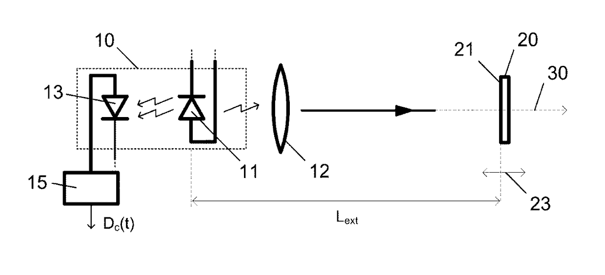
[0027]Another aim of the invention is to provide a measuring device based on the self-mixing effect meeting size, performance and cost constraints making its use in an industrial setting realistic.
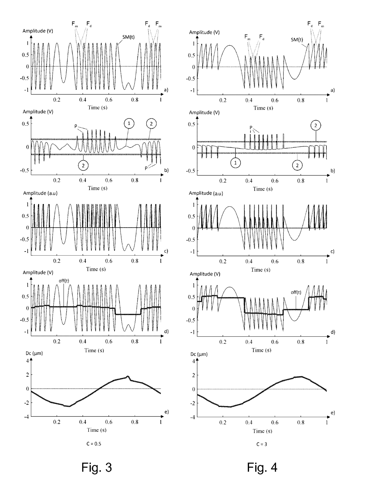
[0072]Determining all of the interferometric peaks of the interferometric signal SM(t) using the processing method defined above in at least one of its modes of implementation advantageously allows the precision of the movement of the target to be improved.

Problems solved by technology

However, for these types of devices, the use of many optical components is necessary, thereby making it difficult to produce compact sensors that are easy to use and inexpensive.
Certain of these devices in addition have a measuring range limited to a few centimeters or even a few millimeters.
Some of the measuring beam is reflected by the target and reinjected into an active cavity of the laser source, producing interference in the active cavity of the laser source.
Existing measuring devices have the drawback of being sensitive to the level of optical feedback to the laser light source.
This effect, known as speckle, leads to strong modulation of the envelope of the interferometric signal, and possibly even to said interference signal being lost, and therefore to a loss of information on the movement of the target, and also adversely affects the processing of the interferometric signal.
This measuring device employs external components that are incompatible with device simplicity and the bulk of which may be incompatible with many applications, especially in the field of on-board systems.
However, the performance of this measuring device is satisfactory only for the type of interferometric signals having a sawtooth waveform with a hysteresis effect, signals typical of highly reflective surfaces and only for target vibrations of small amplitude, at most 180 μm.
In addition, it employs external components, two lenses spaced apart by 40 cm, this being incompatible with the notion of bulk and fragility of the measuring device.
In addition, the device is limited to the measurement of signals of substantially constant amplitude, at the risk of having to restart the autofocus mechanism when the automatically preset threshold is no longer valid.
The three exemplary measuring devices described above must meet a very precise set of specifications (measurement ranges, type of service, bulk, etc.), employ exterior components and cannot easily adapt to changes in operating conditions.

Method used


Image

  • Resetting and hilbert filtering of self-mixing interferometric signal
  • Resetting and hilbert filtering of self-mixing interferometric signal
  • Resetting and hilbert filtering of self-mixing interferometric signal

Examples


example 1

[0186]the target 20 was covered with P40 sandpaper having an average roughness of 425 μm.

[0187]The results obtained are shown in FIGS. 8a to 8d.

[0188]FIG. 8a illustrates the interferometric signal SM(t) measured by the photodiode. It may be seen that the amplitude of the signal is degraded, due to the speckle effect.

[0189]FIG. 8b illustrates the filtered interferometric signal SMf.

[0190]FIG. 8c illustrates the interferometric signal SM(t) and the calculated continuous component Off(t) (all the local components measured per fringe).

[0191]FIG. 8d illustrates the reconstructed movement Dc(t).

[0192]This first example clearly illustrates the fact that the measuring device according to the invention allows the actual movement of a rough target to be reconstructed.

example 2

[0193]the target was covered with a phosphorescent material active in the infrared and exhibiting slow fading, namely the material VRC2 from Thorlabs®.

[0194]The results obtained are shown in FIGS. 9a to 9d.

[0195]FIG. 9a illustrates the interferometric signal SM(t) measured by the photodiode. It may be seen that the amplitude of the signal is clearly more degraded by speckle than for FIG. 8a. It may also be seen that the interferometric signal SM(t) is lost at the times t =0.5 ms and t=2.7 ms.

[0196]FIG. 9b illustrates the filtered interferometric signal SMf.

[0197]FIG. 9c illustrates the interferometric signal SM(t) and the calculated continuous component Off(t).

[0198]FIG. 9d illustrates the reconstructed movement Dc(t).

[0199]This second example perfectly illustrates the fact that the measuring device according to the invention allows the actual movement of a target to be reconstructed even in the presence of a temporary loss of information.

[0200]These examples clearly confirm the ro...


PUM


Abstract

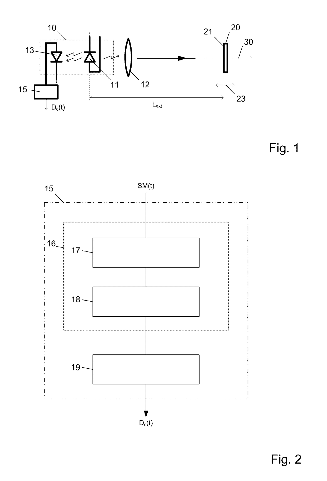
An optical device (10) for determining a physical parameter includes: a laser diode (11) for emitting a beam toward a target; an element for detecting (13) an interferometric signal SM(t) which includes the information on the physical parameter to be determined, and which is generated by an interference between the emitted beam and a light beam reflected by the target; element for converting (15) the signal SM(t) obtained by the detection element (13) into a measurement of the physical parameter, the conversion element (15) including: first element (17) for suppressing a continuous component Off(t) of the interferometric signal SM(t); second element (18) for determining interferometric peaks in the interferometric signal SM(t) obtained from the signal obtained at the output of the first element (17). An associated method, particularly suitable for speckle interferometric signals is also described.

Description

FIELD OF THE INVENTION[0001]The present invention relates to the field of optoelectronic measuring devices. More particularly, the invention relates to an optical device for determining a physical parameter associated with a target and to an associated processing method, whatever the surface finish of the target and its distance, in real-time. The invention is mainly based on self-mixing and is advantageously used to measure the movement of a target.PRIOR ART[0002]There are many types of devices for measuring movement, vibration, distance, etc. of a target, allowing what are called nondestructive measurements to be carried out, i.e. measurements that do not deteriorate the target on which they are performed.[0003]Optical methods are often used because they have the advantage of not requiring contact with the target and are unintrusive. They are based on the transmission of a light beam by a laser light source to a target and on the measurement of changes in the optical properties of...

Claims


Application Information

Patent Timeline
Patent Type & Authority Patents(United States)
IPC IPC(8): G01B9/02G01J9/02
CPCG01J9/02G01B9/02083G01B9/02092
Inventor BOSCH, THIERRYBONY, FRANCISLUNA ARRIAGA, ANTONIO
Owner INST NAT POLYTECHNIQUE DE TOU LOUSE
Why Eureka
Try Eureka