
Liquid ejecting apparatus and method of forming adjustment pattern check area

a technology of liquid ejecting apparatus and adjustment pattern, which is applied in the direction of printing mechanism, spacing mechanism, printing, etc., can solve the problems affecting the adjustment pattern check position, and deteriorating the speed of liquid ejecting at the end of the nozzle array, so as to achieve the effect of reducing the adjustment accuracy

Active Publication Date: 2017-05-30
SEIKO EPSON CORP
View PDF21 Cites 0 Cited by
  • Summary
  • Abstract
  • Description
  • Claims
  • Application Information

AI Technical Summary

Benefits of technology

The patent describes a method for improving the visibility and accuracy of patterns in an inkjet printing system. The method involves using a visibility decrease pattern that decreases the visibility of the patterns in the end region, especially inadequate adjustment pattern check positions. The patterns are organized into groups, and a mark is formed for each pattern set that includes one of each of two or more patterns that correspond to each other. The visibility decrease pattern is formed so that the correspondence between a desired pattern and a mark is easily recognized. The first and second patterns are equal in length in the second direction, which reduces errors in ink-landing position due to variations in ink ejection amounts. The method also ensures point symmetry for simple patterns that are easy for users to see.

Problems solved by technology

In a recording apparatus configured to eject a liquid from a nozzle array, however, the speed of liquid ejection may deteriorate at an end of the nozzle array as disclosed, for example, in JP-A-2012-213909.
Therefore, there may be a decrease in adjustment accuracy if the position of the liquid landing on the medium is adjusted with reference to a part of an adjustment pattern that has been formed by the end of the nozzle array.
Thus, in the liquid ejecting apparatuses of the related art, there may be a decrease in the adjustment accuracy depending on the adjustment pattern check position.
Thus, a decrease in the adjustment accuracy depending on the adjustment pattern check position can be inhibited.

Method used


Image

  • Liquid ejecting apparatus and method of forming adjustment pattern check area
  • Liquid ejecting apparatus and method of forming adjustment pattern check area
  • Liquid ejecting apparatus and method of forming adjustment pattern check area

Examples


Embodiment Construction

[0039]Hereinafter, a recording apparatus serving as a liquid ejecting apparatus according to an embodiment of the invention will be described with reference to the drawings.

[0040]First, an outline of a recording apparatus according to an embodiment of the invention will be given.

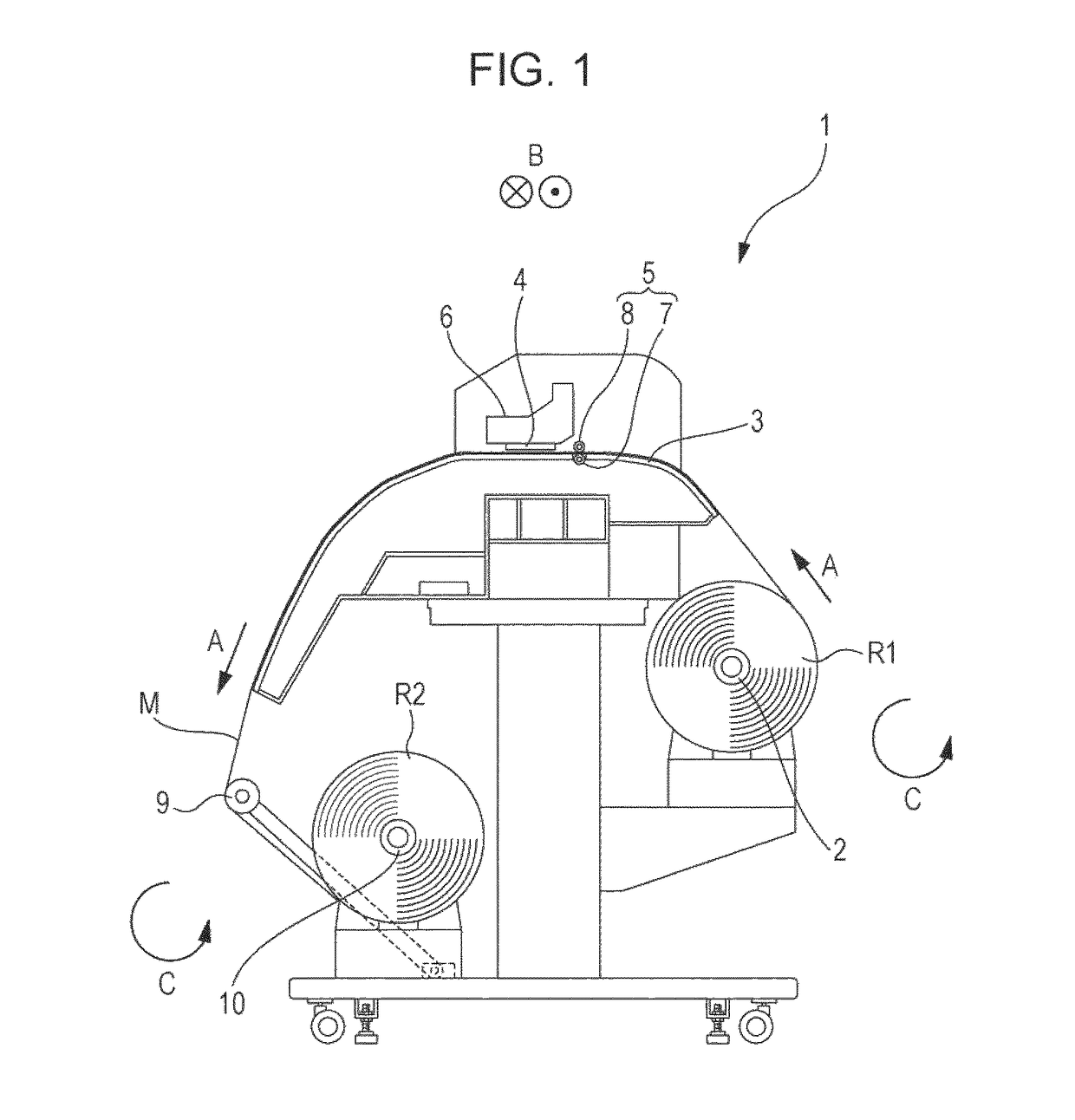
[0041]FIG. 1 is a schematic side view of a recording apparatus 1 according to the present embodiment.

[0042]The recording apparatus 1 according to the present embodiment includes a support shaft 2 that supports a roll R1 that is a subject recording medium (a medium) M in the form of a roll to be used for recording. In the recording apparatus 1 according to the present embodiment, the support shaft 2 rotates in a rotation direction C when the subject recording medium M is transported in a transportation direction A. Note that the present embodiment uses a subject recording medium M wound into a roll in such a way that a subject recording surface thereof is on the exterior, but in the case of using a subject re...


PUM


Abstract

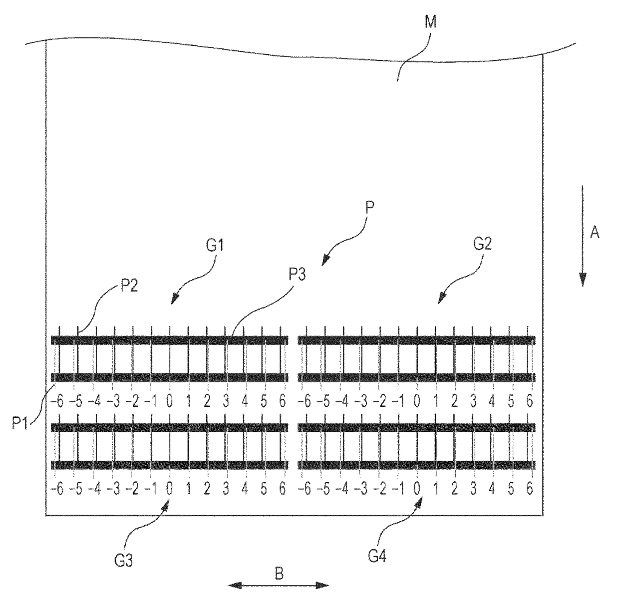
An ejector is caused to eject a liquid such that first patterns are formed in a first direction on a medium while the ejector is moved outward, second patterns are formed in one-to-one correspondence with the first patterns with different first amounts of interval in the first direction from the first patterns while the ejector is moved backward, and a third pattern is formed in an end region that is at least a part of an end of the first patterns in the second direction and at least a part of an end of the second patterns in the second direction.

Description

BACKGROUND[0001]1. Technical Field[0002]The present invention relates to a liquid ejecting apparatus and a method of forming an adjustment pattern check area.[0003]2. Related Art[0004]Liquid ejecting apparatuses, such as for ejecting a liquid, for example, ink, from a nozzle array of an ejector onto a medium such as a subject recording medium, have been used. Generally, such liquid ejecting apparatuses form an adjustment pattern and use the adjustment pattern to adjust the position of the liquid landing on the medium before ejecting the liquid onto the medium.[0005]For example, JP-A-2000-127360 discloses a recording apparatus (a liquid ejecting apparatus) that adjusts the position of a liquid landing on a medium by using a linear pattern formed by a forward movement of an ejector and a linear pattern formed by a backward movement of the ejector.[0006]In a recording apparatus configured to eject a liquid from a nozzle array, however, the speed of liquid ejection may deteriorate at an...

Claims


Application Information

Patent Timeline
Patent Type & Authority Patents(United States)
IPC IPC(8): B41J2/045B41J2/21
CPCB41J2/04505B41J2/04586B41J2/2132B41J2/2135B41J19/145
Inventor YOKOTA, SO
Owner SEIKO EPSON CORP
Learn More