
Optical unit, projection display apparatus, imaging apparatus

a projection display and optical unit technology, applied in the field of optical units, projection display apparatuses, imaging apparatuses, can solve the problems of reducing contrast, increasing the thickness of optical components, and difficult to reduce apparatus thickness, and achieve the effect of thin and high luminance projector optical units

Active Publication Date: 2017-05-30
HITACHI-LG DATA STORAGE
View PDF8 Cites 1 Cited by
  • Summary
  • Abstract
  • Description
  • Claims
  • Application Information

AI Technical Summary

Benefits of technology

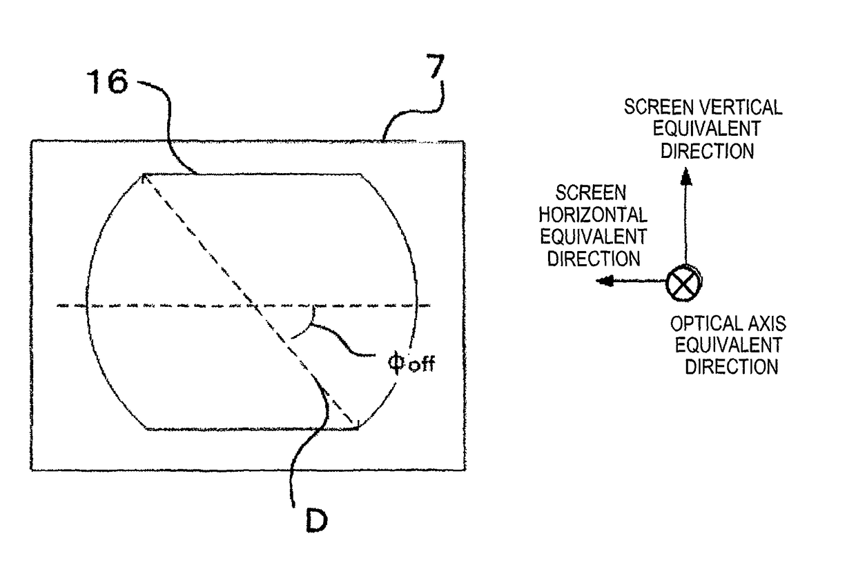
[0008]One method for achieving high luminance is to reduce the F-number of an illumination light beam. However, reducing the F-number causes an overlap between an OFF light beam and an ON light beam, thereby reducing the contrast. Accordingly, a conventional method needs to increase the opening diameter by reducing the F-number only in a screen vertical equivalent direction. Since this direction is equivalent to the vertical direction (that is, the thickness direction) in a conventional apparatus, the light beam diameter in the thickness direction of the apparatus increases and the thickness of the optical component increases, thereby making it difficult to reduce the thickness of the apparatus.
[0009]The invention addresses this problem, with an object of providing a thin and high luminance projector optical unit, a projection display apparatus having the projector optical unit, and an imaging apparatus having the projector optical unit by improving the efficiency while reducing the thickness of the illumination optical system.
[0011]The invention has an effect of providing a thin and high luminance projector optical unit, a projection display apparatus having the projector optical unit, and an imaging apparatus having the projector optical unit.

Problems solved by technology

However, reducing the F-number causes an overlap between an OFF light beam and an ON light beam, thereby reducing the contrast.
Since this direction is equivalent to the vertical direction (that is, the thickness direction) in a conventional apparatus, the light beam diameter in the thickness direction of the apparatus increases and the thickness of the optical component increases, thereby making it difficult to reduce the thickness of the apparatus.

Method used


Image

  • Optical unit, projection display apparatus, imaging apparatus
  • Optical unit, projection display apparatus, imaging apparatus
  • Optical unit, projection display apparatus, imaging apparatus

Examples


Embodiment Construction

[0024]Examples of embodiments of an optical unit according to the present invention and a projection display apparatus and an imaging apparatus that have the optical unit will be described with reference to the drawings. The invention is not limited by the following description. In the drawings, components with the same functions are denoted by the same reference characters.

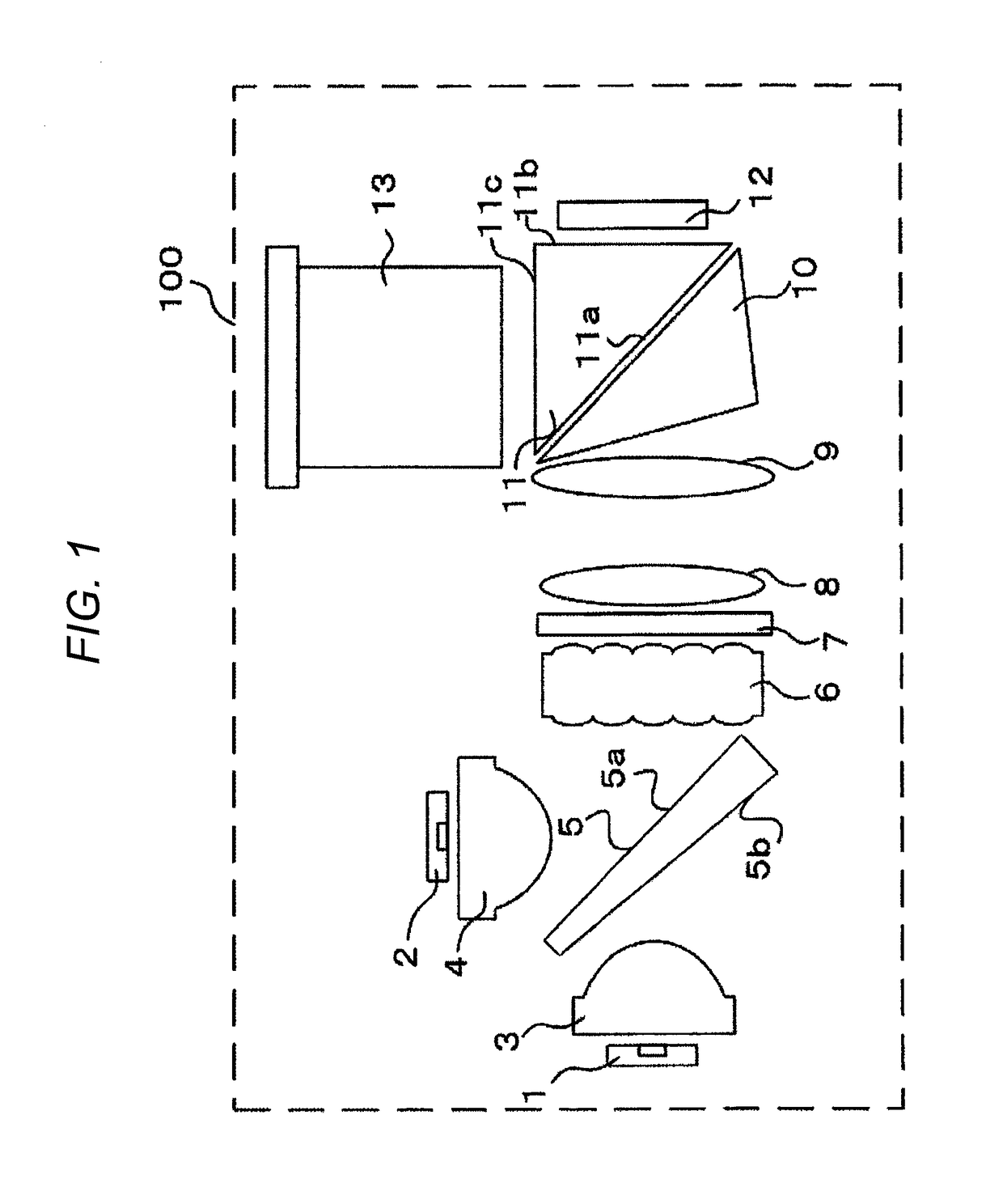
[0025]FIG. 1 is a block diagram showing an optical unit 100 in the embodiment.

[0026]The optical unit 100 has light sources 1 and 2, each of which emits a light beam of a predetermined wavelength or waveband.

[0027]The light source 1 is, for example, an LED light source that emits a green light beam with a center wavelength of approximately 525 nm. The light source 2 is, for example, an LED light source having a two-color light-emitting source that emits a red light beam with center wavelength of approximately 615 nm and a blue light beam with a center wavelength of approximately 460 nm. The center wavelengths are ...


PUM


Abstract

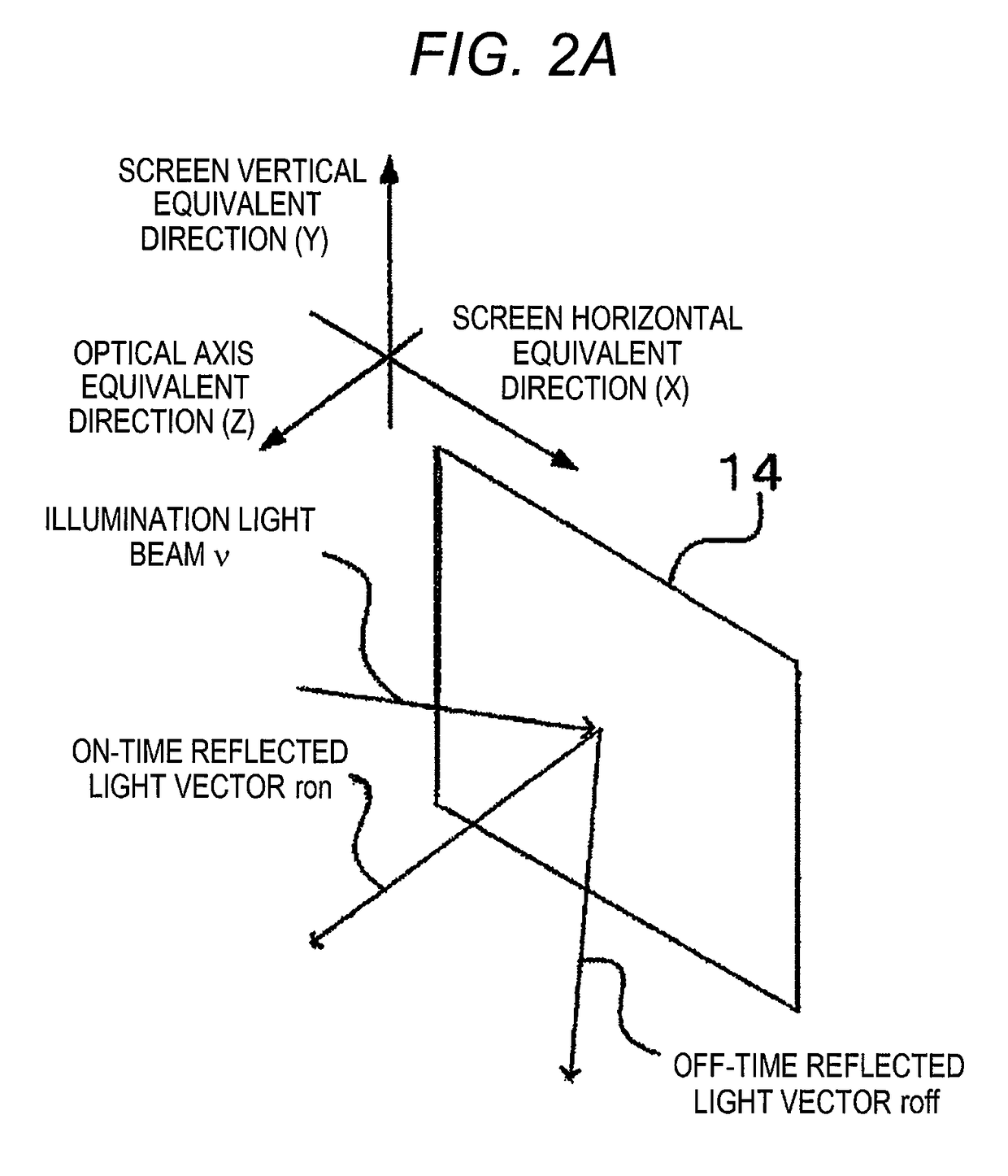
In an optical unit having a reflective picture display device for displaying pictures by projecting light, the picture display device has a first state in which focused light is reflected in an optical axis equivalent direction of an image to be displayed and a second state in which focused light is reflected so as to have a component in a vertical equivalent direction of an image to be projected, a plane including an entire optical axis of light reflected in the second state differs from a plane formed by the optical axis of light incident on the picture display device and the optical axis of light reflected by the picture display device in the first state, and the opening size of the opening of an illumination lens in a horizontal equivalent direction of the image to be projected is larger than in the vertical equivalent direction.

Description

CROSS-REFERENCE TO RELATED APPLICATION[0001]This application claims the priority of Japanese Patent Application No. 2013-251042 Filed Dec. 4, 2013, which is incorporated herein by reference in its entirety.BACKGROUND OF THE INVENTION[0002]1. Field of the Invention[0003]The present invention relates to an optical unit projecting a picture on a screen using a light source and picture display device and to a projection display apparatus and an imaging apparatus that have the optical unit.[0004]2. Description of the Related Art[0005]In a projection display apparatus (that is, a projector), a DMD (Digital Micromirror Device), which is one of micromirror picture display devices, is attracting attention as a picture display device capable of achieving a small and high luminance optical unit. The DMD performs optical modulation by individually controlling the angle of a micromirror provided for each pixel to divide DMD incident light into a direction (ON light) in which the light is inciden...

Claims


Application Information

Patent Timeline
Patent Type & Authority Patents(United States)
IPC IPC(8): G03B21/00H04N5/74H04N9/31G03B21/28G03B21/20
CPCG03B21/008H04N5/7458H04N9/315G03B21/208G03B21/2013G03B21/2033G03B21/28
Inventor NAKAMURA, TOSHITERUOUCHI, SATOSHI
Owner HITACHI-LG DATA STORAGE
Learn More