Emergency alert system

a technology of emergency alert and emergency response, applied in the direction of alarms, instruments, etc., can solve the problem of critical time required to summon an emergency first responder to the scene of a traumatic injury

Inactive Publication Date: 2017-05-30
RACHAL FRANK G
View PDF10 Cites 4 Cited by
  • Summary
  • Abstract
  • Description
  • Claims
  • Application Information

AI Technical Summary

Benefits of technology

[0007]These and other features of the present invention will become rea...

Problems solved by technology

In particular, the time required to summon an emergency ...

Method used


Image

  • Emergency alert system
  • Emergency alert system
  • Emergency alert system

Examples


Embodiment Construction

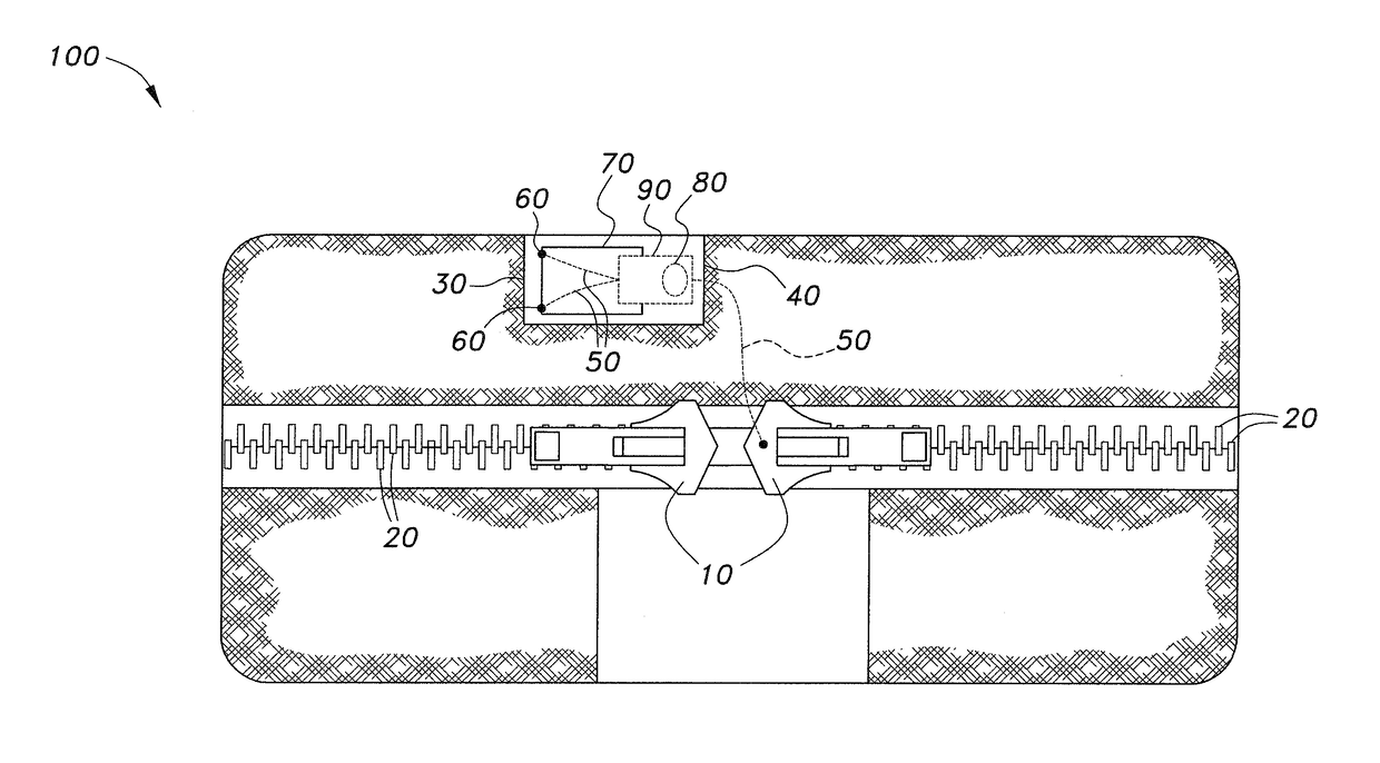
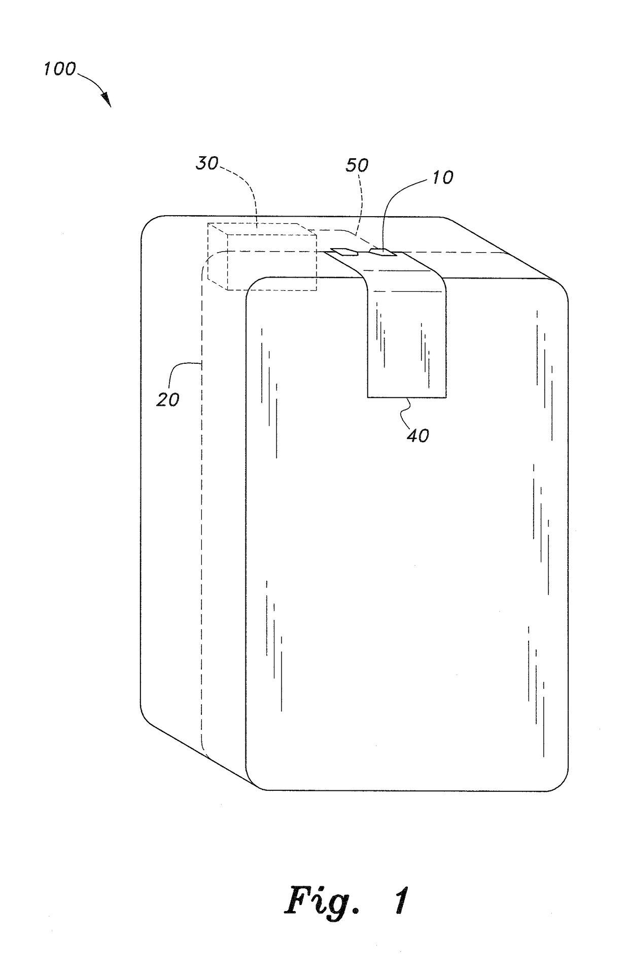
[0014]The emergency alert system 100 (an example of which is shown in FIG. 1) may include a device / emergency kit container that includes a zipper slider 10, a zipper 20, access tab 40, alert device 30 and non-conductive pull tab 50.

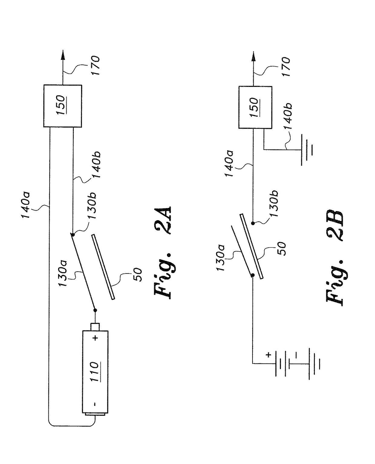
[0015]As shown in FIGS. 2A and 2B, a battery-operated circuit may include a battery 110 having its negative terminal connected to a first lead 140a and a spring biased switch throw 130a. A switch pole 130b is connected to a second lead 140b. The first and second leads 140a and 140b are connected to a device 150 that is actuated when the battery-operated circuit is closed. The non-conductive pull tab 50 is removably disposed between the switch throw 130a and pole 130b, thus keeping the circuit open until the non-conductive pull tab is pulled away from the switch throw 130a and switch pole 130b mechanism. The open configuration of the battery operated circuit is shown in FIG. 2B, where the pull tab 50 is disposed between the switch throw 130a and the switch...


PUM


Abstract

The emergency alert system may include a device/emergency kit container, or may be incorporated into a belt, harness, or other personal protective equipment. The system may include a zipper slider, a zipper, access tab, alert device, and non-conductive pull tab. When the non-conductive pull tab is pulled, the alert device is triggered, and alerts monitors that an emergency situation has occurred involving traumatic injury and alerting the monitors of the location of the emergency situation.

Description

BACKGROUND OF THE INVENTION[0001]1. Field of the Invention[0002]The present invention relates to emergency alert devices and systems, and more particularly to an emergency alert system that provides a switch-actuated emergency alert device for providing or summoning assistance to a person or a location.[0003]2. Description of the Related Art[0004]Trauma, regardless of its source (gunshots, stabbings, serious falls, car accidents, natural disasters, etc.) is the leading cause of death among Americans under the age of forty-five, accounting for more fatalities than illness and infectious disease combined. Emergency first responders have developed a protocol to handle traumatic injuries, which includes early recognition, early treatment, and quick access to a medical facility. In particular, the time required to summon an emergency first responder to the scene of a traumatic injury is critical. The survival rate in traumatic injuries is substantially related to emergency response time....

Claims


Application Information

Patent Timeline
IPC IPC(8): G08B25/01
CPCG08B25/016
Inventor RACHAL, FRANK G.
Owner RACHAL FRANK G
Why Eureka
Try Eureka