Electronic cigarette

a technology of electronic cigarettes and soldering operations, applied in tobacco, applications, food science, etc., can solve the problems of high product defective rate of electronic cigarettes, low production efficiency, and inability to easily achieve soldering operations, so as to improve the production efficiency of electronic cigarettes, the distance between the electrode terminals can be designed to be wider, and the soldering operation is easy to achieve

Inactive Publication Date: 2017-06-06
HUIZHOU KIMREE TECH
View PDF1 Cites 39 Cited by
  • Summary
  • Abstract
  • Description
  • Claims
  • Application Information

AI Technical Summary

Benefits of technology

[0030]By implementing the electronic cigarette in the present application, the following advantages can be achieved. The electronic cigarette adopts that the conductive wire is soldered on the first electrode terminal, the second electrode terminal or the third electrode terminal of the mounting seat, so that the conductive wire is electrically connected to the controlling module. As the electrode terminals on the mounting seat are not limited by circuit structure, the distance between the electrode terminals can be designed to be wider, and soldering operation can be easily achieved, which can improve production efficiency of the electronic cigarettes and decrease product defective rate. Furthermore, it can cut down the number of soldering points and further improve the production efficiency of the electronic cigarettes that one selected from the first electrode terminal, the second electrode terminal and the third electrode terminal is connected to the conductive wire by soldering.

Problems solved by technology

When a structure that the first conductive wire 400, the second conductive wire 500 and the third conductive wire 600 are respectively connected to the controlling module 300 by welding is adopted, a welding operation is not easily achieved, which leads to low production efficiency and high product defective rate of electronic cigarettes.

Method used


Image

  • Electronic cigarette
  • Electronic cigarette
  • Electronic cigarette

Examples


Embodiment Construction

[0040]To make the technical feature, objective and effect of the present application be understood more clearly, now the specific implementation of the present application is described in detail with reference to the accompanying drawings and embodiments.

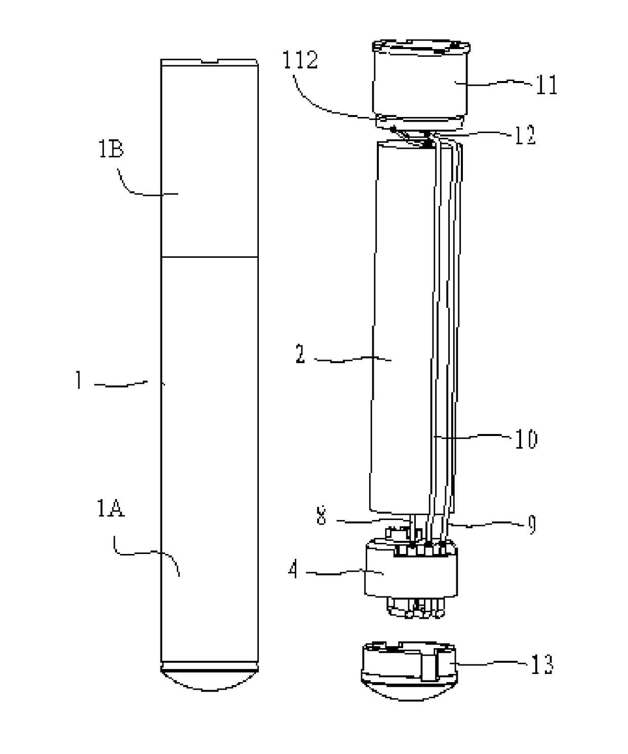
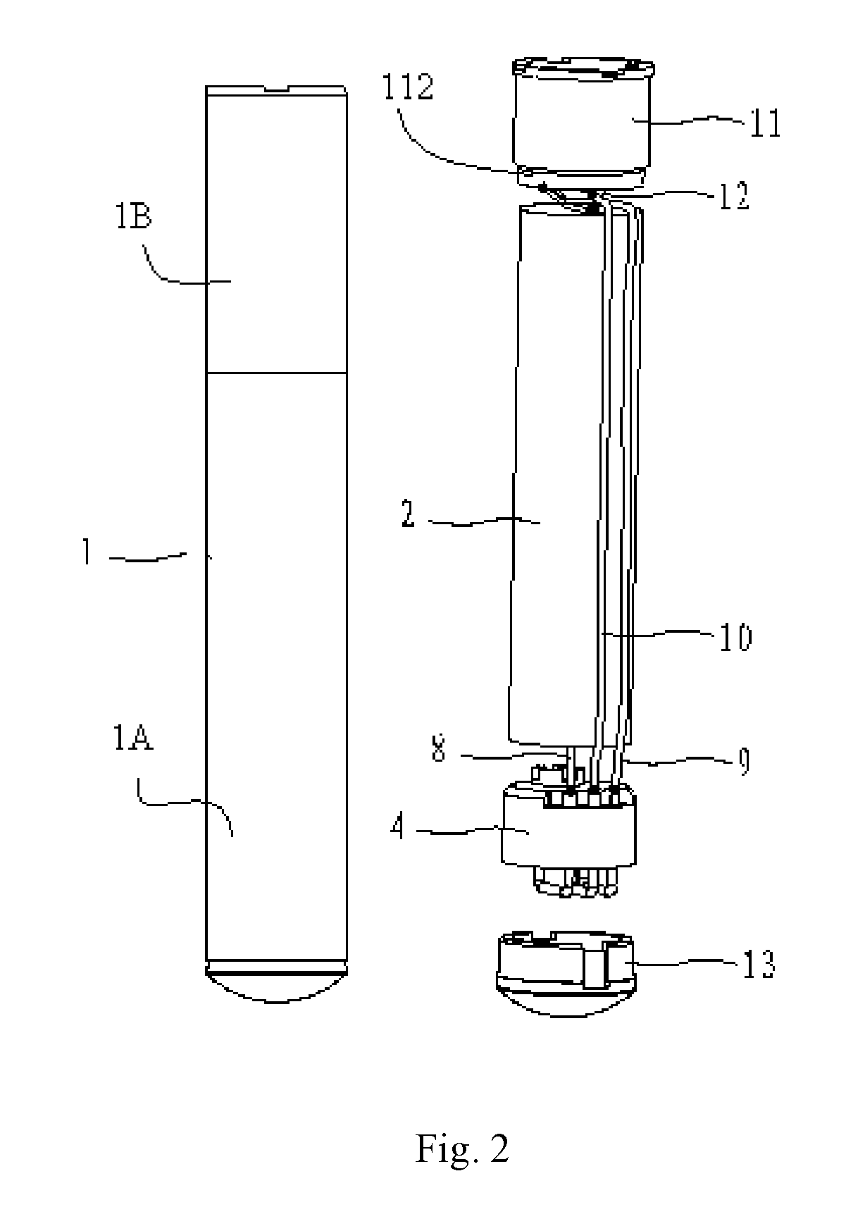
[0041]As shown in FIG. 2 and FIG. 4, a first preferred embodiment of the present application provides an electronic cigarette comprising an outer sleeve 1, a battery 2, a controlling module 3, a mounting seat 4, a first electrode terminal 5, a second electrode terminal 6, a third electrode terminal 7, a first conductive wire 8, a second conductive wire 9, a third conductive wire 10, a first electrode connecting member 11, a second electrode connecting member 12, a lamp assembly 13 and an insulating ring 112. The outer sleeve 1 is approximately a hollow cylindrical structure.

[0042]As shown in FIG. 3, the battery 2 includes a battery body 20, a first electrode 21 and a second electrode 22. The first electrode 21 and the second electro...


PUM


Abstract

An electronic cigarette is provided, and the electronic cigarette comprises an outer sleeve, a battery and a controlling module both mounted inside the outer sleeve; the electronic cigarette further comprises a mounting seat which the controlling module is mounted on, and an electrode terminal mounted on the mounting seat and electrically connected to the controlling module; an end of the electrode terminal, aloof from the controlling module, is connected to a conductive wire by soldering. By implementing the electronic cigarette in the present application, the following advantages can be achieved. The electronic cigarette adopts that the conductive wire is soldered on the first electrode terminal, the second electrode terminal or the third electrode terminal, so that the conductive wire is electrically connected to the controlling module, and soldering operation can be easily achieved, which can improve production efficiency of the electronic cigarettes and decrease product defective rate.

Description

CROSS-REFERENCE TO RELATED APPLICATIONS[0001]This non-provisional application claims priorities under 35 U.S.C. §119(a) on Patent Application No. 201320449480.0 filed in P.R. China on Jul. 25, 2013, the entire contents of which are hereby incorporated by reference.FIELD OF THE INVENTION[0002]The present application relates to the field of consumer electronic products, and more particularly relates to an electronic cigarette.BACKGROUND OF THE INVENTION[0003]As shown in FIG. 1, the existing electronic cigarette comprises an outer sleeve 100, a battery assembly and an atomizer assembly both mounted inside the outer sleeve 100. The battery assembly includes a battery 200, a controlling module 300, a first conductive wire 400, a second conductive wire 500 and a third conductive wire 600, above three conductive wires are respectively soldered on the controlling module 300. The controlling module 300 integrates an air flow sensor and a control circuit and so on. The first conductive wire 4...

Claims


Application Information

Patent Timeline
Patent Type & Authority Patents(United States)
IPC IPC(8): A24F47/00A24F40/40A24F40/50
CPCA24F47/008A24F40/50A24F40/40
Inventor LIU, QIUMING
Owner HUIZHOU KIMREE TECH
Why Eureka
Try Eureka