Oil mist collector

a technology of oil mist collector and air purification device, which is applied in the direction of dispersed particle separation, transportation and packaging, and separation processes, etc., can solve the problems of overheating, broken or overheating in operation, and exhaust clean and fresh air, so as to reduce air resistance and pressure loss, the effect of high recycling

Active Publication Date: 2017-06-06
AIR O FILTER ENVIRONMENT SYST
View PDF3 Cites 3 Cited by
  • Summary
  • Abstract
  • Description
  • Claims
  • Application Information

AI Technical Summary

Benefits of technology

[0011]The primary objective of the present invention is to provide an oil mist collector which facilitates enhancing flow speed and flow rate of oil mists and reducing air resistance and pressure loss in a filtration process, thus enhancing filtering and recycling effect.
[0018]Since the air guiding orifice is located above the second air chamber and communicates with the second filtering unit, the others of the oil mists are pumped upwardly into the second filtering unit from the second air chamber smoothly. In other words, a flowing path of the air flow in the casing unit is shorten greatly to reduce the air resistance and the pressure loss, thus causing smooth exhaustion and high recycling to the oil mists.

Problems solved by technology

A conventional oil mist filter is mounted on a working machine to filter oil mists, dusts, smokes, and hazes which produce in working process, thus exhausting clean and fresh air.
However, the oil mist filter still has following disadvantages:
In order to overcome such a problem, the motor has to rotate at a high speed to enhance the flow rate of the oil mists, so it is broken or is overheat in operation.

Method used


Image

  • Oil mist collector
  • Oil mist collector
  • Oil mist collector

Examples


first embodiment

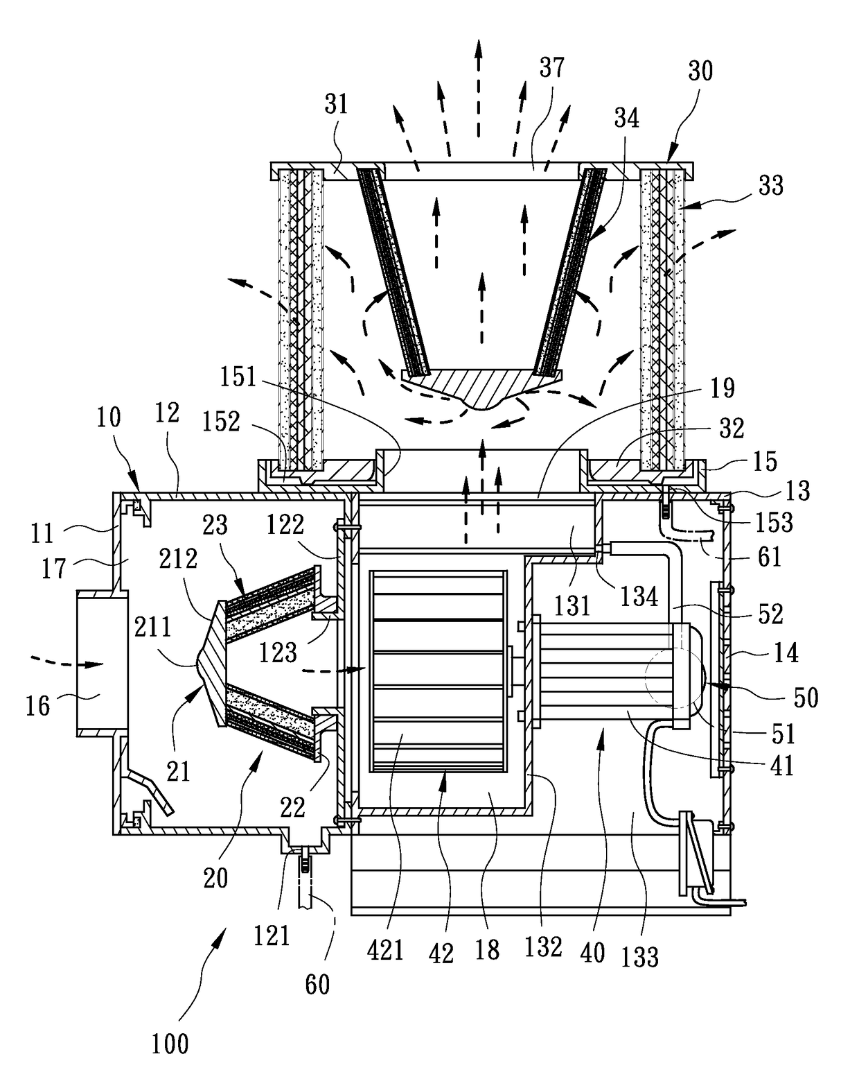
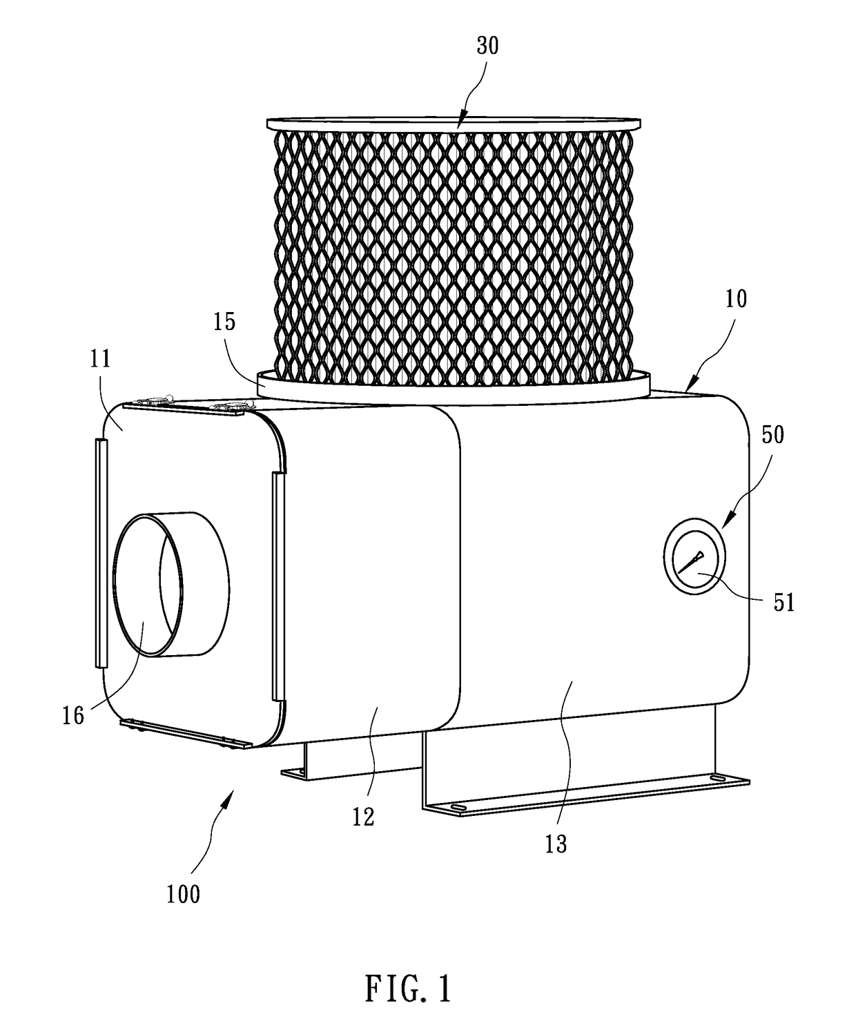
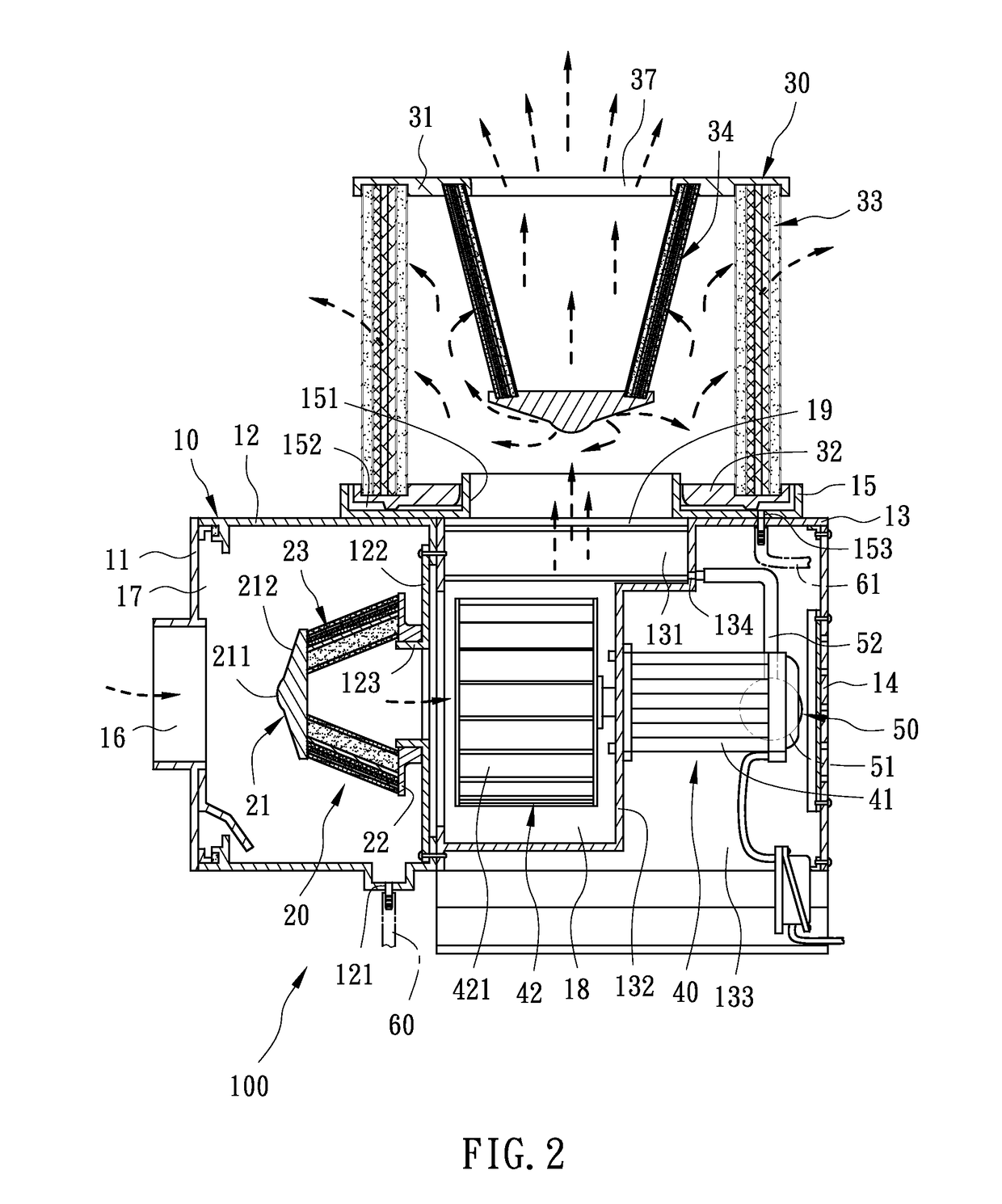
[0028]With reference to FIGS. 1 and 2, an oil mist collector 100 according to the present invention is fixed on a work table of a machine (not shown). The oil mist collector 100 comprises: a casing unit 10, a first filtering unit 20, a second filtering unit 30, a ventilation unit 40, and a pressure indicator 50.

[0029]Referring to FIGS. 2 and 3, the casing unit 10 includes a first cap 11, a first box 12 connected with the first cap 11, a second box 13 proximate to the first box 12, a second cap 14 disposed on a rear end of the second box 13, and a holder 15 mounted on a top end of the second box 13, wherein the first cap 11, the first box 12, and the second box 13 define a hollow interior to accommodate an inlet 16, a first air chamber 17, a second air chamber 18, and an air guiding orifice 19 located above the second air chamber 18 and communicating with an exterior environment. The first cap 11 has the inlet 16 formed on a central portion thereof and is removed to open the first ai...

second embodiment

[0043]Referring further to FIGS. 6 to 8, the first filtering unit 20 is disposed in the first air chamber 17 in a rotatable connecting manner according to the present invention, wherein an air tube 123 has a plurality of L-shaped slots 124 formed on a peripheral wall thereof, and a first filtering unit 20 includes plural locking elements 24 arranged on a second lip 22 thereof, wherein each locking element 24 is a screw bolt and its central axis is perpendicular to a center of the second lip 22, such that each locking element 24 is rotatably screwed with each L-shaped slot 124, and the second lip 22 of the first filtering unit 20 is connected with an air baffle 122 tightly to fix the air tube 123 securely.

third embodiment

[0044]As shown in FIG. 9, in a third embodiment, a second filtering unit 30 includes a second filtration assembly 33 and a third filtration assembly 35 surrounded by the second filtration assembly 33 in the second filtering unit 30, wherein the second filtration assembly 33 is parallelly defined between a third lip 31 and a fourth lip 32, and each of the second filtration assembly 33 and the third filtration assembly 35 has a plurality of filter layers, wherein the third lip 31 is covered by a cover 36, hence the second filtration assembly 33 and the third filtration assembly 35 filter oil mists, dusts, and waste gases.


PUM

PropertyMeasurementUnit
inclination angleaaaaaaaaaa
shapeaaaaaaaaaa
air resistanceaaaaaaaaaa

Abstract

An oil mist collector contains a casing unit, a first filtering unit, a second filtering unit, and a ventilation unit. The casing unit includes an inlet, a first air chamber, a second air chamber, an air guiding orifice corresponding to the second air chamber and communicating with an exterior, and a first recycling orifice arranged on a bottom end thereof and communicating with the first air chamber. The first filtering unit is disposed in the first air chamber and corresponds to the inlet. The second filtering unit is fixed above the air guiding orifice and includes an open rear end, a first lip with a noncircular cross section, a second lip, and a first filtration assembly defined between the first lip and the second lip. The ventilation unit includes a motor and a rotary fan rotatably connected with the motor and secured in the second air chamber.

Description

BACKGROUND OF THE INVENTION[0001]1. Technical Field[0002]The present invention relates to an air purifying apparatus, and more particularly to an oil mist collector which facilitates enhancing flow speed and flow rate of oil mists and reducing air resistance and pressure loss in a filtration process, thus enhancing filtering and recycling effect.[0003]2. Description of Related Art[0004]A conventional oil mist filter is mounted on a working machine to filter oil mists, dusts, smokes, and hazes which produce in working process, thus exhausting clean and fresh air.[0005]Another conventional oil mist filter is disclosed in TW Publication No. M436140 and contains a frame, a casing, a filtering unit, a ventilation unit, and a filtration cylinder mounted outside the casing. The frame has a filtering space and a pumping space, and a bottom end of the pumping space is in connection with an oil collection space. The filtering unit is disposed in the filtering space and has an arcuate turbulen...

Claims


Application Information

Patent Timeline
Patent Type & Authority Patents(United States)
IPC IPC(8): B01D46/00B01D50/00B01D46/24
CPCB01D46/0023B01D46/0002B01D46/003B01D46/0024B01D46/0031B01D46/0084B01D46/2411B01D50/002B01D2273/30B01D2275/201B01D2275/208B01D46/64B01D50/20B01D46/62
Inventor LEE, TUNG-TSAI
Owner AIR O FILTER ENVIRONMENT SYST
Why Eureka
Try Eureka