
Method and arrangement for clarifying green liquor

a filtering method and green liquor technology, applied in the pulp industry, can solve the problems of low filtering capacity, unplanned and unplanned operation, and large sedimentation apparatus, and achieve the effect of facilitating constant flow rate or constant reynold number

Active Publication Date: 2017-02-23
CLEANFLOW
View PDF2 Cites 0 Cited by
  • Summary
  • Abstract
  • Description
  • Claims
  • Application Information

AI Technical Summary

Benefits of technology

This approach significantly enhances filtering efficiency, maintaining high separation degrees of dregs, reducing investment costs, and minimizing energy consumption while allowing for incremental capacity increases with minimal investment, resulting in a continuous process with almost 100% dregs removal and reduced operational expenses.

Problems solved by technology

The chemical recovery is very often a bottleneck in the production of cellulose pulp and when the mills raise the production there is a need of raising the capacity of the chemical recovery process.
Building larger apparatus for sedimentation of the green liquor is, however, a costly and complicated choice since the diameter the tank becomes large.
It is of great importance to keep the sludge content a low level in the cooking chemicals, otherwise the sludge will cause scaling and plugging in the pulping plant and the evaporation plant, which leads to unwished and unplanned, costly operation stops.
A general problem with filtration of green liquor is the low filtering capacity because of the poor filterability of the green liquor.
The dregs in the green liquor form a dense cake on the filtering layer and blind the filtering medium thus lowering the filtering capacity even more.
The filter cake must be removed and thereby causing production stops leading to lowered productivity and higher operating costs.
A problem with prior art technique described above is the low filtering efficiency leading to large equipments and with high investment costs and a relative high energy consumption.

Method used


Image

  • Method and arrangement for clarifying green liquor
  • Method and arrangement for clarifying green liquor
  • Method and arrangement for clarifying green liquor

Examples


Embodiment Construction

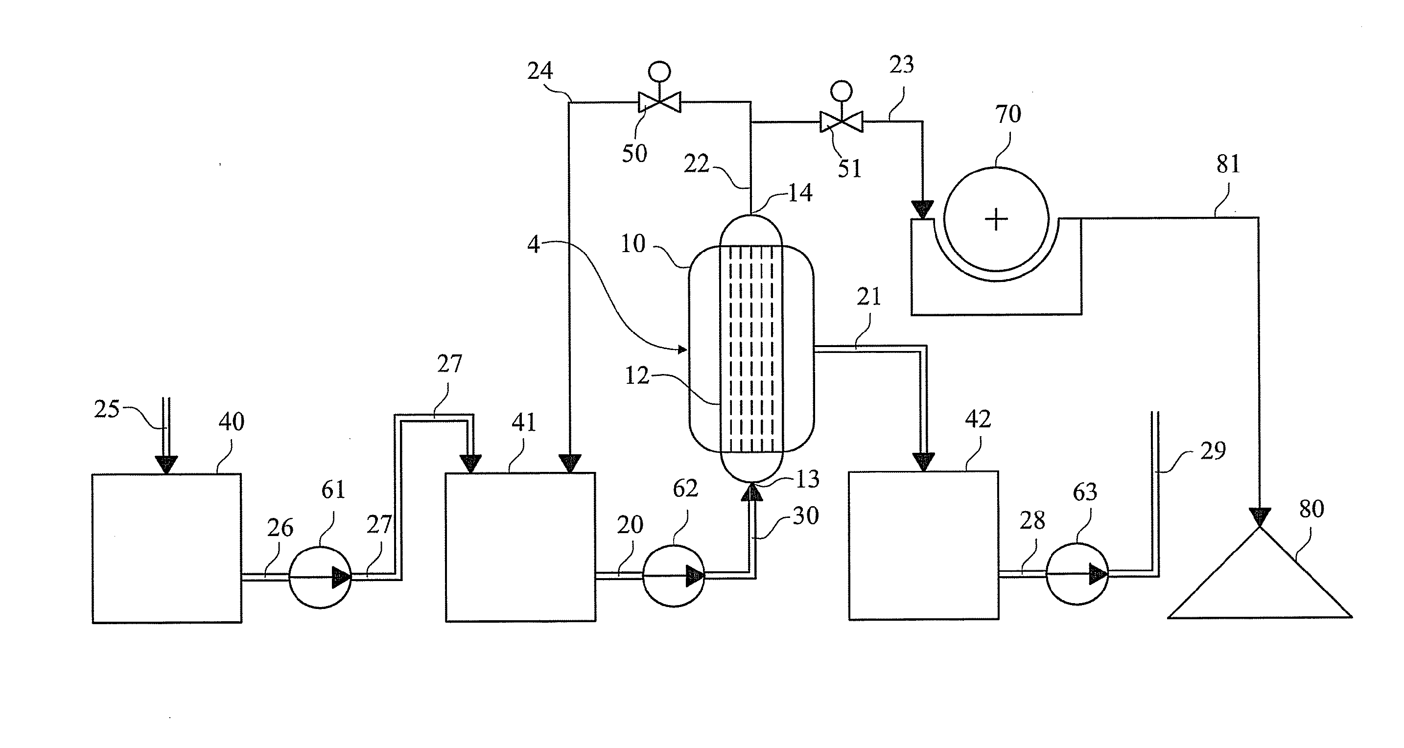
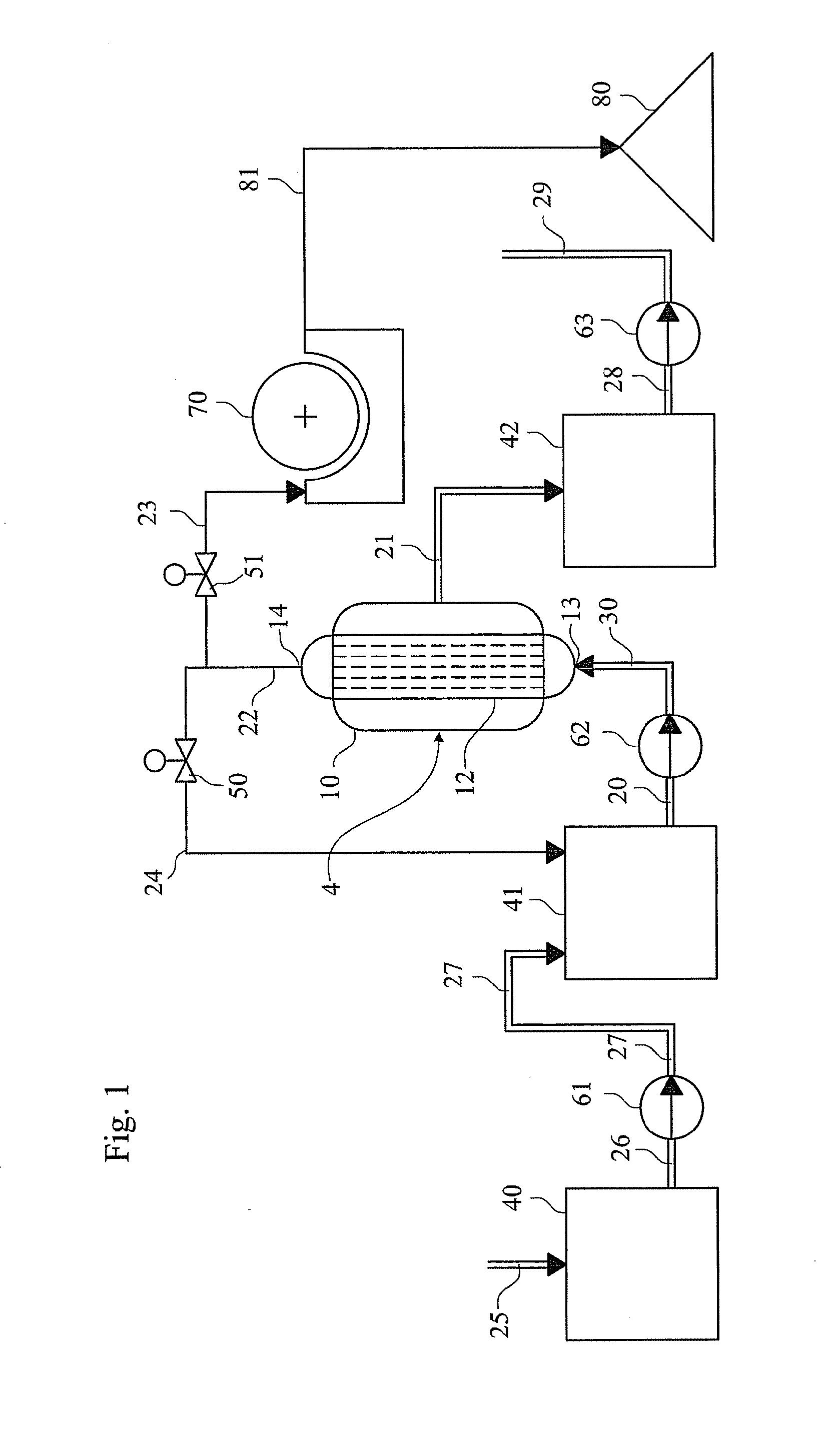
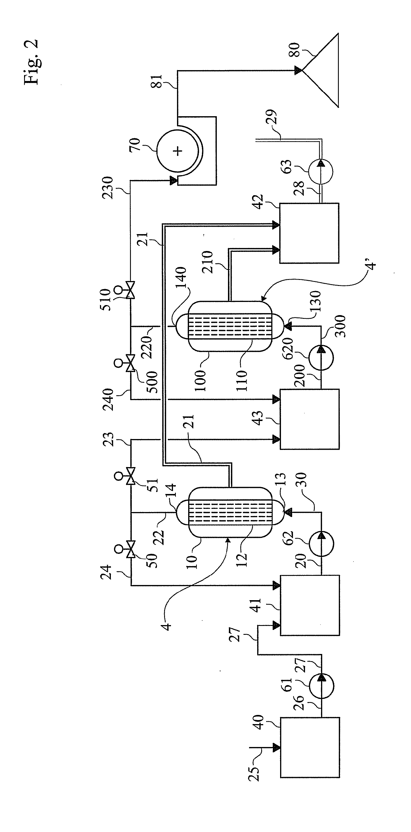
[0032]The cross-flow filter consists of a filter unit comprising one or several filter elements. These filter elements are provided with a plurality of filter bodies, each filter body comprising a filter channel.

[0033]The filter body also comprises porous filter walls surrounding the channels. Each filter body comprises a supporting structure and in conjunction with the filter walls, which may be integral therewith. In a preferred embodiment the filtering layer is applied as a coating on the inside of the supporting structure. The coating may in some preferred installations have filter pores of a filter pore size of 0.2 to 1.0 micrometer. In other installations other pore sizes may be more advantageous, but would normally be within the range 0.1 to 10 micrometer.

[0034]The filter walls in this embodiment may be made of a ceramic material. The interior diameter of the filter channels provided within the filter elements is 1-10 mm and the length of the filter channels is preferably 0.5...


PUM

PropertyMeasurementUnit
pore sizeaaaaaaaaaa
pore sizeaaaaaaaaaa
pore sizeaaaaaaaaaa

Abstract

Green liquor clarification comprising filtering of a flowing suspension containing solids, wherein the suspension is brought into contact with a first filter unit (4), said 5 filter unit (4) comprising one or several filter elements (12) comprising one or several filter bodies (3) having filter channels (33) within the filter bodies (3) with a filtering layer (32), a part of the suspension is forced to pass through the filtering layer (32) from a first / inner surface (32A) to a second / outer surface (32B) of the filtering layer (32) forming a filtrate while the solids substantially remains in a residual part of the suspension forming a slurry and where the filtering layer (32) is made of a membrane material with pores, said pores having a pore size of 0.1-10 micrometer, more preferred 0.1-5 micrometer and most preferred 0.2-1.0 micrometer.

Description

FIELD OF THE INVENTION[0001]The present invention relates to the pulp industry, more specifically to the chemical recovery of the chemical pulping process. The invention describes a filtering method and arrangement for clarifying green liquor.BACKGROUND INFORMATION[0002]During the pulping of the chips lignin and other substances in the chips are dissolved into the pulping liquid.[0003]In order to recover the pulping chemicals (as well as to produce energy) the black liquor is concentrated and then sent to a recovery boiler. The concentrated black liquor is combusted in the recovery boiler and heat is extracted from the hot flue gases. The sodium and sulfur compounds are recovered as sodium carbonate and sodium sulfide. The sodium carbonate and sodium sulfide exit the recovery boiler in a molten state and are dissolved in a water solution (weak white liquor) thus forming green liquor.[0004]The green liquor formed also contains small amounts of solid material, known as green liquor dr...

Claims


Application Information

Patent Timeline
Patent Type & Authority Applications(United States)
IPC IPC(8): D21C11/00B01D69/04B01D61/14B01D71/02
CPCD21C11/0078B01D71/02B01D69/04B01D2317/02B01D2311/25B01D2325/02B01D61/142B01D61/147B01D2325/02834B01D2311/252B01D29/356B01D69/02
Inventor LINDSTROM, MIKAELLINDGREN, CHRISTOFERBORJESON, LENNARTKALLEN, LENNART
Owner CLEANFLOW
Learn More