Battery charge circuit with multi-charge stage and method thereof

a charge circuit and battery technology, applied in electric vehicles, electric power, transportation and packaging, etc., can solve the problems of increasing the difficulty of charging the difficulty of continuous delivery of constant charge current into the batteries, and the inability to fully charge the energy into the batteries, so as to reduce the generation of lead sulfate, reduce the capacity of the batteries, and increase the li

Inactive Publication Date: 2007-06-21
SUNJETT CORP
View PDF22 Cites 8 Cited by
  • Summary
  • Abstract
  • Description
  • Claims
  • Application Information

AI Technical Summary

Benefits of technology

[0011] According to the embodiments, using pulses to charge batteries may reduce generation of the lead sulfate during the charge. Therefore, batteries may have full charge and the life-span increases.
[0012] According to the embodiments, the charge current in pulse form may be applied to the batteries for maintenance after charging batteries. The low temperature causes batteries capacity to decrease in cool or cold region. The pulses provided after charging prevents the capacity decrease. Therefore, extra apparatuses or electrical maintenance devices for maintenance after charge is not necessary.
[0013] According to the embodiments, there are multi charge stages. The stage is adjustable according the charge state of the batteries. The charge efficiency is improved and time saving.

Problems solved by technology

The charge method illustrated in FIG. 1˜3 may not fully charge the energy into the batteries.
Further, the constant charge current in the conventional charge method is difficult to deliver into the battery continuously.
Thus, charge energy into the batteries becomes more and more difficult.
Besides, the ageing of batteries also arise difficulty of charge.
Lead Sulfate not only results in unfull charge of the batteries, but also decrease of life-span.
The low temperature causes batteries capacity to decrease in cool or cold region.

Method used


Image

  • Battery charge circuit with multi-charge stage and method thereof
  • Battery charge circuit with multi-charge stage and method thereof
  • Battery charge circuit with multi-charge stage and method thereof

Examples


Embodiment Construction

[0039] Reference will now be made in greater detail to an embodiment of the invention, an example of which is illustrated in the accompanying drawings. Wherever possible, the same reference numerals are used throughout the drawings and the description to refer to the same or like parts.

[0040] Reference in the specification to “one embodiment” or “an embodiment” means that a particular feature, structure, or characteristic described in connection with the embodiment is included in at least one embodiment of the invention. The appearances of the phrase “in one embodiment” in various places in the specification are not necessarily all referring to the same embodiment.

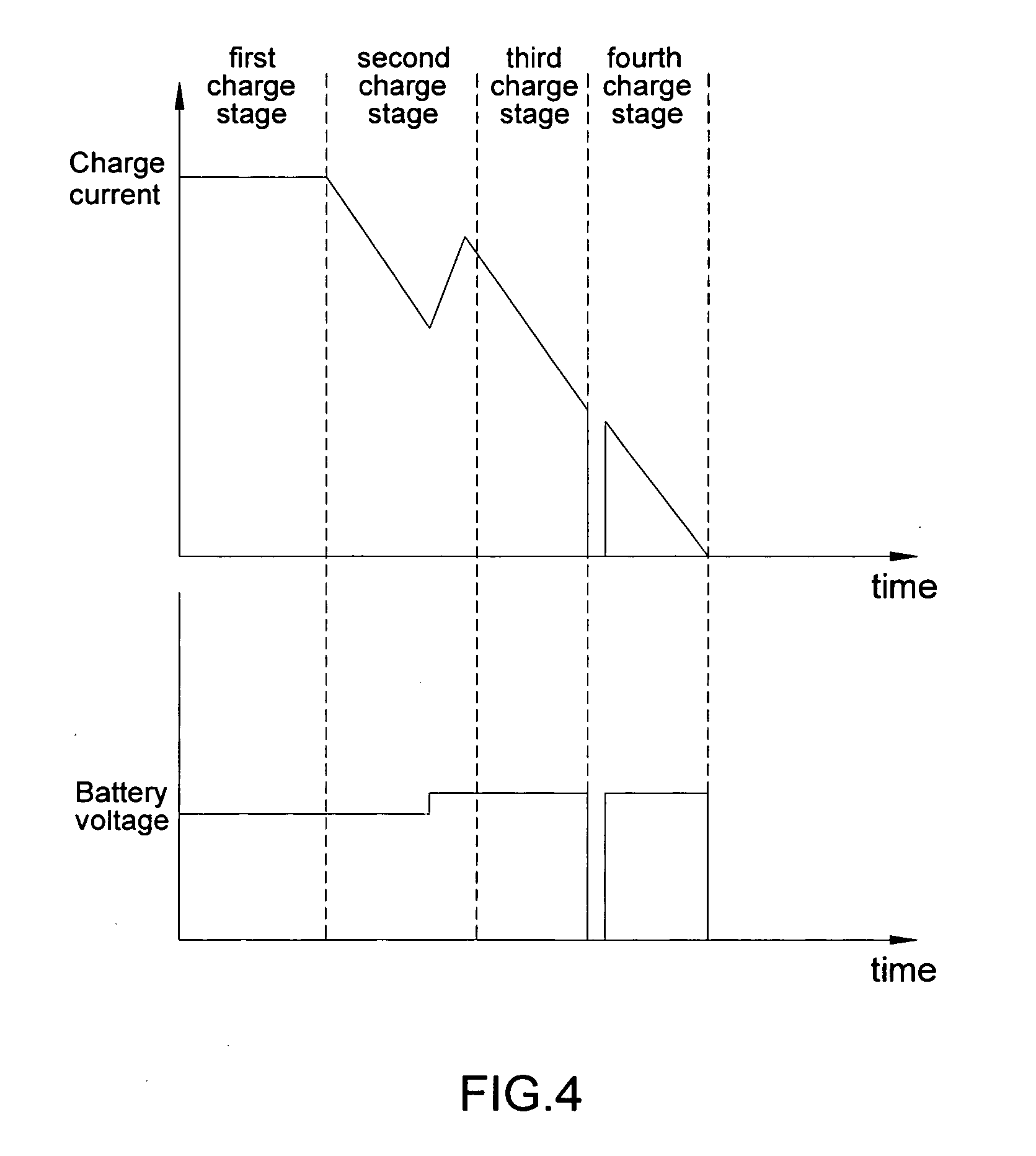
[0041]FIG. 4 illustrates a charge topology of the invention. In FIG. 4, a multi charge stage charge topology is employed. The main charge stages are the first charge stage, the second charge stage, the third charge stage, and the fourth charge stage respectively. In the embodiment, in the first charge stage, constant cur...


PUM


Abstract

A charge circuit having multi charge stages for charging at least one battery includes: a first current generating circuit for generating a first charge power having a first charge current in pulse form with a first frequency and a first charge voltage to charge the at least one battery; a voltage generating circuit connected to the first current generating circuit for controlling the first charge power having a first charge current in pulse form with a first frequency and a first charge voltage; a voltage control circuit connected to the voltage generating circuit for generating a first constant voltage and/or a second constant voltage; and a second current generating circuit connected to the voltage generating circuit for generating a variant power comprising a variant current in pulse form with a second frequency wherein a charge voltage included in the variant power varies with the second frequency.

Description

BACKGROUND [0001] 1. Field of the Invention [0002] The invention relates to a charge circuit / method and in particular to a charge circuit / method using charge current and voltage in pulses to charge batteries. [0003] 2. Related Art [0004] Batteries of all shapes and sizes, available in sealed and maintenance-free products, are mass-produced today. Batteries are commonly used to provide a direct-current (dc) source of electrical energy in a wide variety of applications. [0005] Battery charging is accomplished through delivery of an external power source to a battery, thereby ionizing the plates to opposing potentials (voltages or electrical pressures) and reversing the electrochemical process that occurs when the battery is used to supply energy to a load. Refer to FIG. 1 depicting a charge topology of half constant current. The voltage in the battery increases with time, while the charge current decreases gradually. Refer to FIG. 2 depicting a charge topology of constant current. In ...

Claims


Application Information

Patent Timeline
Patent Type & Authority Applications(United States)
IPC IPC(8): H02J7/00
CPCH02J7/0073H02J7/0071
Inventor LIN, SHENG-CHAN
Owner SUNJETT CORP
Why Eureka
Try Eureka