Storage battery

Active Publication Date: 2006-09-28
GS YUASA INT LTD
View PDF2 Cites 9 Cited by
  • Summary
  • Abstract
  • Description
  • Claims
  • Application Information

AI Technical Summary

Benefits of technology

[0038] According to the invention set forth in claim 7, since two opposed ones of the grid wires surrounding each of the meshes are longer than the other two opposed grid wires, the mesh has a substantial parallelogram shape having long and short sides of different lengths. When grid wires on the side which receives higher tension during the expanding step in the rotary method are set to the long sides, therefore,

Problems solved by technology

Consequently, an expand grid produced by the rotary method has a further disadvantage that the grid wires 1b are easily ruptured or cracked during the production process to lower the production yield and impair the life performance.
In the case where such an expand grid is used as a positive plate of a lead storage battery, however, an oxidation reaction of lead or a lead alloy occurs during a charging process, and the reaction proceeds to sometimes cause the grid wires 1b to be cracked by oxidation corrosion.
When the grid wires 1b in the vicinity of the collector frame portion 1a are cracked, therefore, a larger quantity of the active material are electrically isolated, with the result that the capacity of the battery plate is greatly reduced.
In both expand grids produced by the rotary and reciprocal methods, when the expand grids are produced so that the grid wires 1b have different widths, grid wires 1b of a narrower width are easily cracked, thereby causing a problem in that the yield is lowered.
When the widths of such grid wires 1b of the lateral end rows are smaller than or equal to those of the grid wires of the other rows, particularly, the grid wires are easily cracked.
The rotary production method has the advantages of a high spe

Method used


Image

  • Storage battery
  • Storage battery
  • Storage battery

Examples


embodiment (

3) of the Invention

[0078]FIG. 6 shows a third embodiment of the invention, and is a partial enlarged plan view of an expand grid in which a mesh is expanded in an expanding step in the rotary method, into a parallelogram shape having different long and short sides.

[0079] In the embodiment also, a storage battery in which an expand grid produced by the rotary method is used as a battery plate will be described.

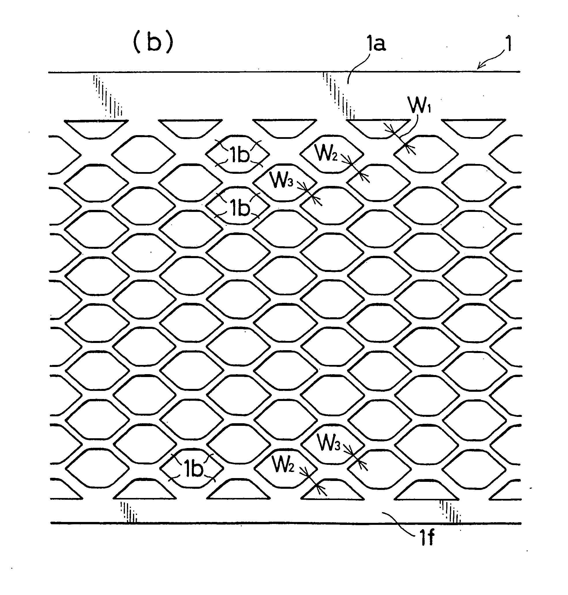
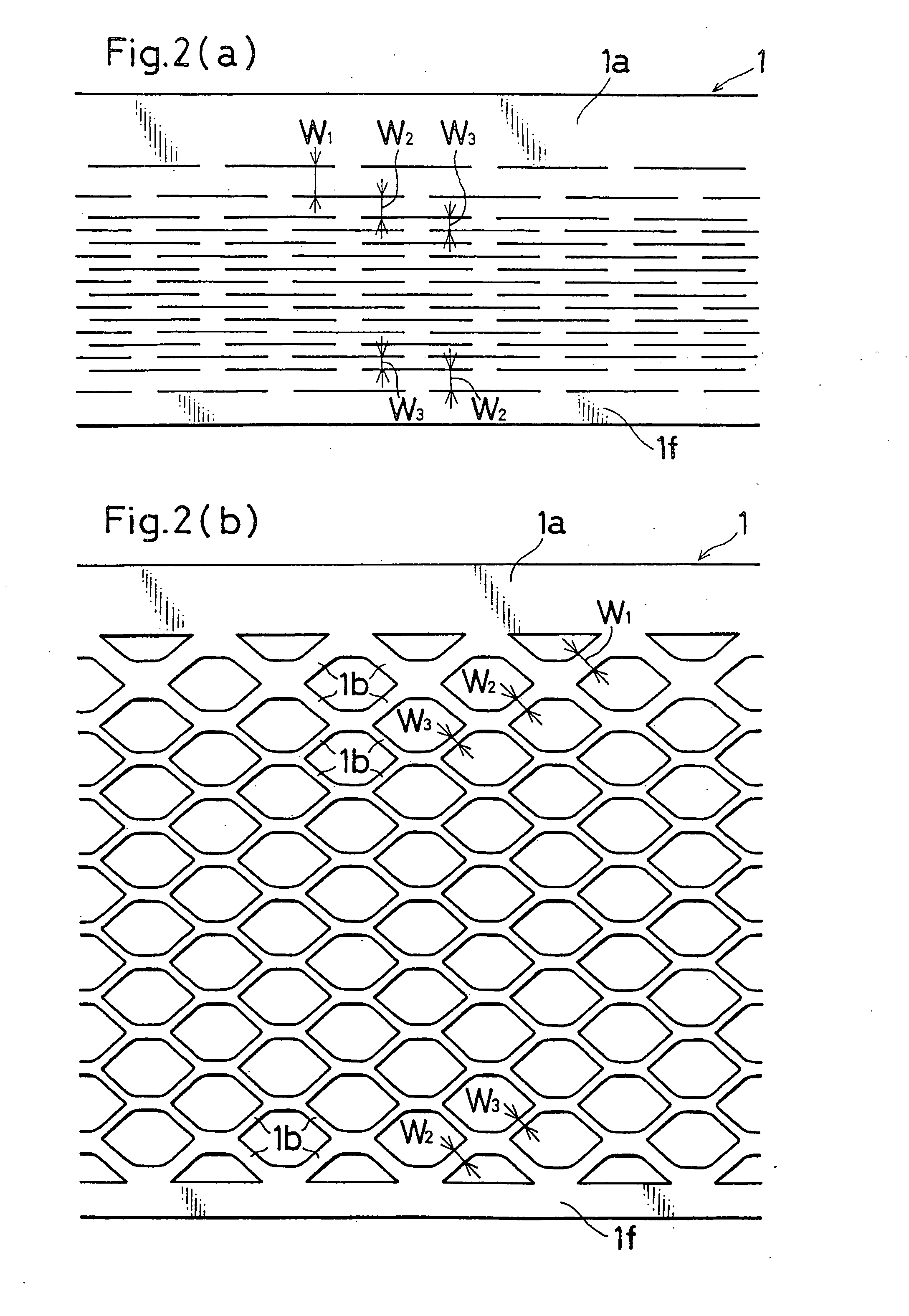
[0080] As shown in FIG. 6, the meshes 1c of the expand grid which is produced by the rotary method have a substantial parallelogram shape, except those which are adjacent to the collector frame portion 1a, and which have a substantially triangular shape. Namely, each of the meshes 1c is configured by the four nodes 1e which are positioned respectively at the apexes of the parallelogram, and the four grid wires 1b which connect the nodes 1e to one another.

[0081] As shown in FIG. 18, each of the meshes 1c of the conventional expand grid which is produced by the rotary method h...

example 1

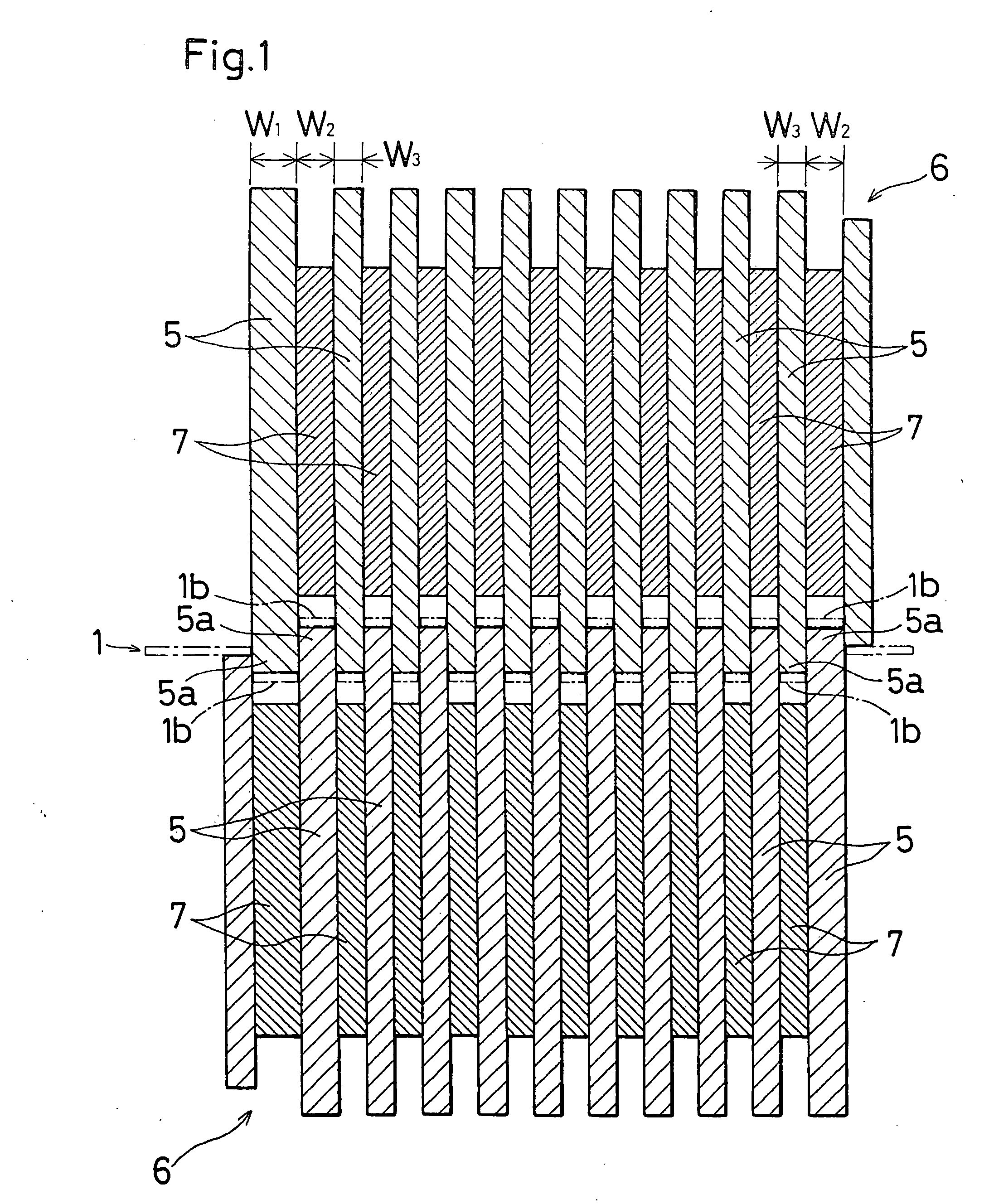
[0085] Example 1 is an example of the first embodiment, and shows comparison between the case where the grid wires 1b which are directly connected to the lower frame portion 1f that is remotest from the collector frame portion 1a of the metal sheet 1 shown in FIG. 2 were set to have the smallest width, and that where the grid wires were set to have a larger width.

[0086] In Example 1, an alloy sheet of Pb-0.06 wt. % Ca-1.0 wt. % Sn was processed into expand grids by using the rotary production method. When the grid wires 1b of the row which is directly connected to the lower frame portion 1f that is remotest from the collector frame portion 1a were set to have the smallest width by adequately changing the thicknesses of disk cutters and spacers of a rotary expanding machine, a crack of corrosion was observed in 10% of the connections of the grid wires 1b and the lower frame portion 1f, during the expanding step. By contrast, when the grid wires 1b of the row which is directly connec...

example 2

[0088] Example 2 is an example of the first embodiment, and shows comparison between the case where the grid wires 1b which are directly connected to the collector frame portion 1a of the metal sheet 1 shown in FIG. 2 were set to have the smallest width, and that where the grid wires were set to have a larger width.

[0089] In Example 2 also, an alloy sheet of Pb-0.6 wt. % Ca-1.0 wt. % Sn was processed into expand grids by using the rotary production method. An anode active material for a lead storage battery which was produced in the usual way was filled into the expand grids produced by the rotary production method, and the grids were then cured and dried to form positive plates for a lead storage battery. A cathode active material for a lead storage battery which was produced in the usual way was filled into identical expand grids, and the grids were then cured and dried to form negative plates for a lead storage battery.

[0090] Such positive and negative plates were alternately s...


PUM

PropertyMeasurementUnit
Fractionaaaaaaaaaa
Fractionaaaaaaaaaa
Fractionaaaaaaaaaa

Abstract

A storage battery is provided in which an expand grid is improved with respect to the widths of grid wires 1b, the sectional areas of nodes 1e, and the shapes of meshes 1c, whereby the productivity of the expand grid can be enhanced and the life performance can be improved. As means for attaining the object, a storage battery in which an expand grid is used as a battery plate, the expand grid being a grid member which is formed by expanding a side portion of a collector frame portion 1a of a metal sheet 1 to connect a large number of grid wires 1b to one another in a net-like shape, is configured so that widths of grid wires 1b of a row which is directly connected to the collector frame portion 1a of the expand grid, and a lateral end row are larger than widths of grid wires 1b of at least one of intermediate rows.

Description

BACKGROUND OF THE INVENTION [0001] The present invention relates to a storage battery in which an expand grid is used as a battery plate. [0002] A grid which is to be used as a battery plate for a lead storage battery is sometimes produced by the expansion process. Methods of producing an expand grid by the expansion process are roughly classified into two kinds or the rotary method and the reciprocal method. [0003] In the reciprocal method, an expand grid is produced in the following manner. Dice cutters which are arranged in a stepwise manner are vertically moved on a metal sheet that is intermittently moved, to sequentially form slits in the metal sheet, and the metal sheet is then stretched to be formed into a net-like shape. Specifically, as shown in FIG. 11, a metal sheet 1 made of lead or a lead alloy is intermittently transported on a flat upper face of a lower table 2 in the direction of the arrow F. Step-like side faces 2a are formed on the side faces of the lower table 2,...

Claims


Application Information

Patent Timeline
IPC IPC(8): H01M4/74H01M4/04
CPCH01M4/745Y10T29/10Y10T29/49108Y02E60/10
Inventor FUJIWARA, YOSHIOMITANAKA, HIROYUKI
Owner GS YUASA INT LTD
Why Eureka
Try Eureka