Side curtain air bag

a side curtain and air bag technology, applied in the direction of vehicular safety arrangements, pedestrian/occupant safety arrangements, vehicle components, etc., can solve the problems of increasing affecting the safety of passengers, and occupants may be injured rather than protected by the expansion force, etc., to achieve low tension, increase the tension across the air bag, and high tension

Inactive Publication Date: 2007-07-19
AUTOLIV DEV AB
View PDF25 Cites 17 Cited by
  • Summary
  • Abstract
  • Description
  • Claims
  • Application Information

AI Technical Summary

Benefits of technology

[0020] The air bag according to the present invention includes the primary chamber which expands to develop the air bag; the secondary chamber which applies an additional tension on the developed air bag, and the secondary chamber gradually expands later than the primary chamber is expanded. Therefore, it is possible to gradually increase the tension across the entire air bag. Accordingly, it is easy to properly control the tension of the air bag.
[0021] As a result, at the initial stage of the collision, the air bag protects the head of occupants while maintaining relatively low tension across the entire air bag so as to be soft, and at the latter stage of the collision, the air bag prevents the occupants from being thrown out of the vehicle by turnover accidents by maintaining relatively high tension across the air bag when developed to the fullest.
[0022] Further, the secondary chamber is disposed such that a portion or the entire secondary chamber overlaps a virtual band. The virtual band region may be defined by of a first virtual line connecting the respective fixation ends of the one set of tethers and a second virtual line connecting the respective joint ends of the one set of tethers; the virtual band region may also be formed of a first virtual line connecting respective upper ends of attachment points of the one set of tethers and a second virtual line connecting respective lower ends of the attachment points of the one set of tethers; and the virtual band region may be formed of a first virtual line connecting the upper end of the attachment part of one tether and the fixation end of the other tether, and a second virtual line connecting respective lower ends of the attachment points of the one set of tethers. Therefore, the tension created by the expansion of the secondary chamber, after the primary chamber is expanded and developed, is applied on the primary chamber along the virtual band region. As a result, it is possible to prevent the occupants from being thrown out of the vehicle by turnover accidents or the like by maintaining high tension of the entire air bag following initial expansion.

Problems solved by technology

Therefore, when the air bag expands, if the expansive force of the air bag 103 is excessively high and makes the air bag 103 too hard, the expansive force may harm rather than protect the occupant.
Therefore, in the prior art it is difficult to make the tension across the air bag low when the air bag initially starts to expand and develop, and become high when the air bag is developed.

Method used


Image

  • Side curtain air bag
  • Side curtain air bag
  • Side curtain air bag

Examples


Embodiment Construction

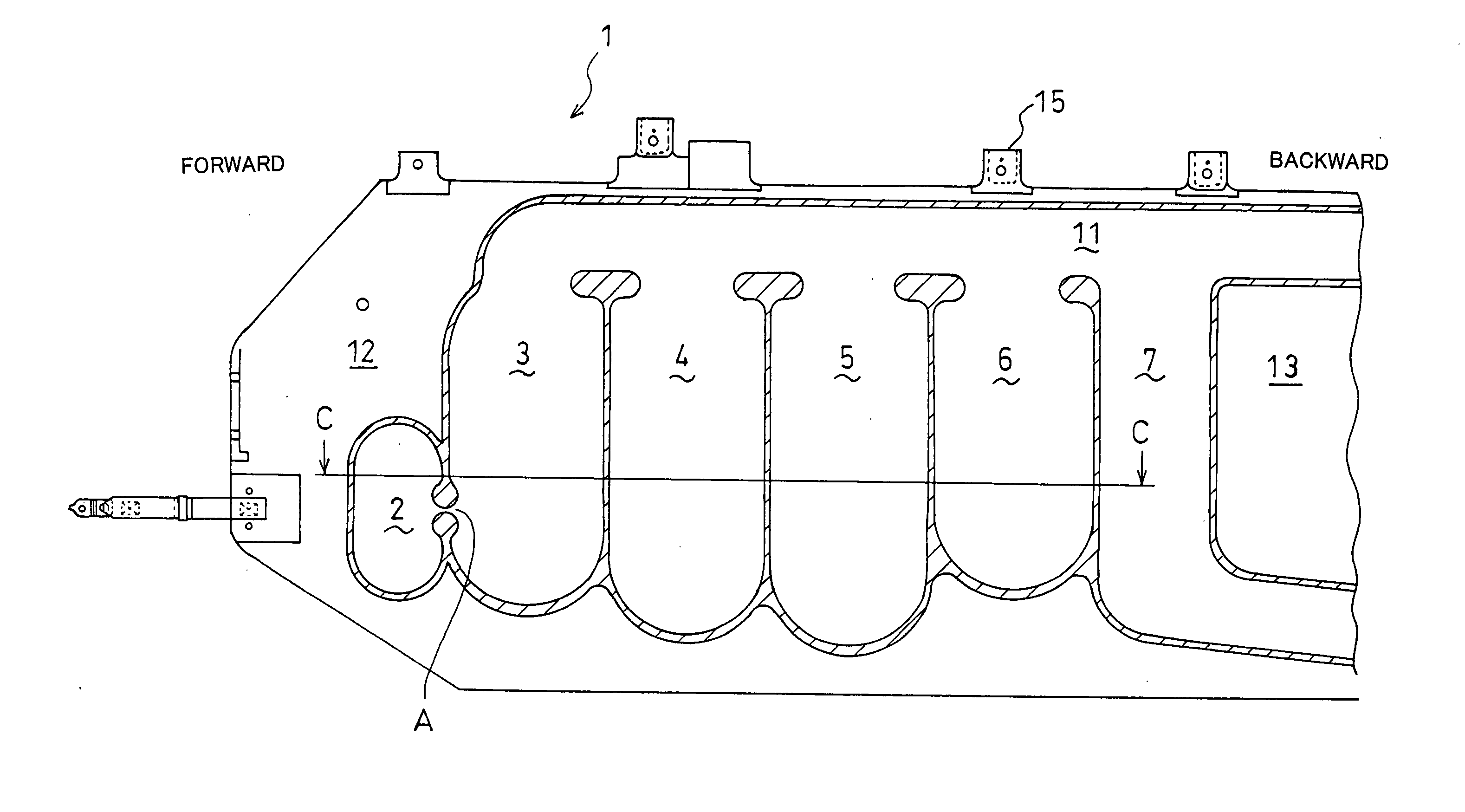
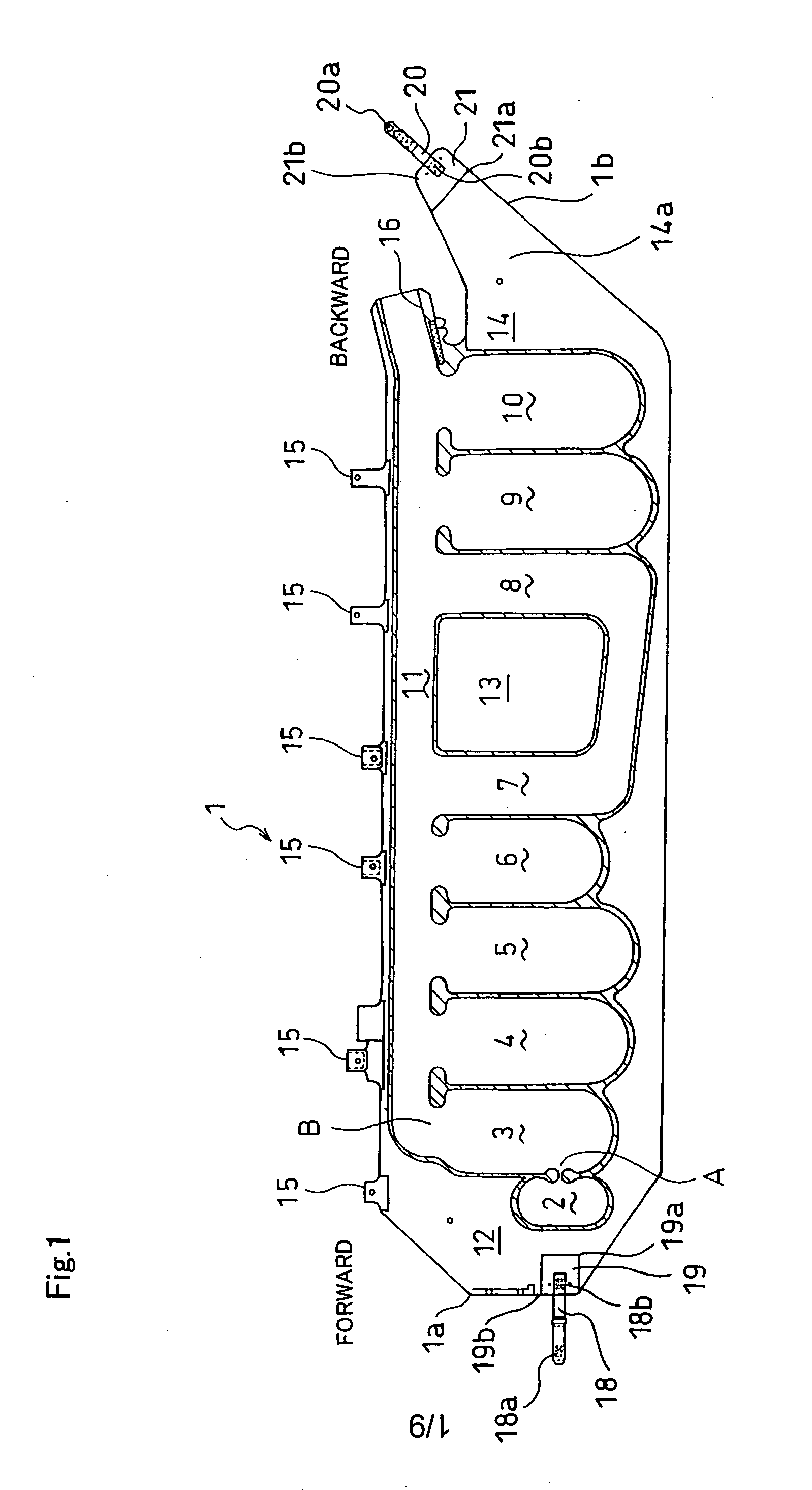
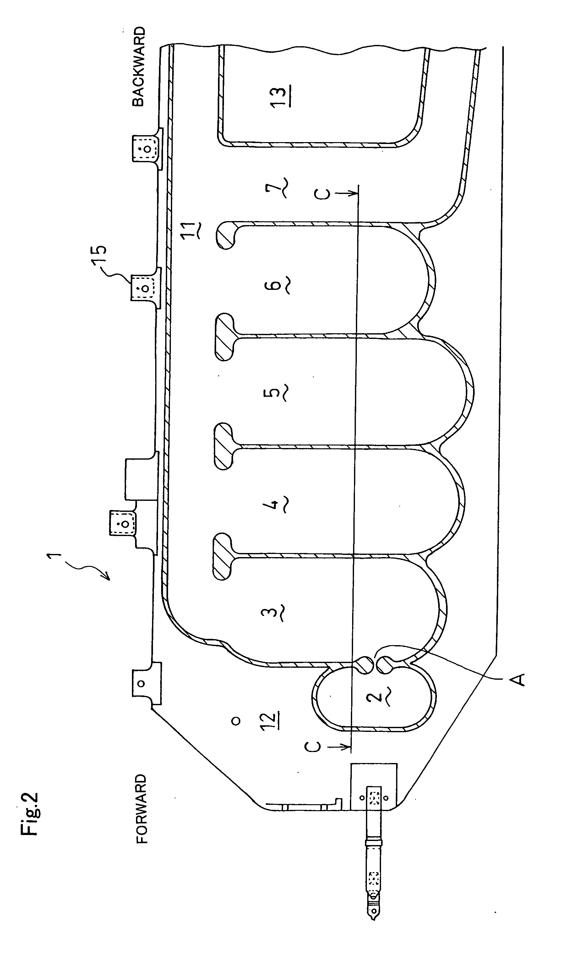
[0033] An air bag 1 according to a first embodiment of the present invention will be described with reference to FIG. 1 which shows a cross-sectional view of the air bag 1. FIG. 2 is an enlarged view of the air bag 1 of FIG. 1. FIG. 3 is a cross-sectional view of the air bag 1 taken along the line C-C of FIG. 2. FIG. 4 is a graph showing the internal pressure change of primary chamber 3 and secondary chamber 2 according to the embodiment of FIG. 1.

[0034] In addition, in reference to the air bag of the present invention, the descriptions forward, backward, left, and right refer to the directions in which the air bag is attached to the inside of a vehicle as the air bag 1 expands and develops into a curtain shape.

[0035] The air bag 1 according to a first embodiment of the present invention is a pouch-shaped air bag formed by integrally superimposing a sheet of flexible material having the section shown in FIG. 1 upon another sheet of material having a section that is a mirror image ...


PUM


Abstract

The present invention provides a side curtain air bag facilitating the control of tension with the airbag. The side curtain air bag includes chambers expanded by gas supplied from a gas generator, and expands and develops into a curtain shape along a side part of a vehicle so as to protect vehicle occupants. The side curtain air bag includes primary chambers which expand to form the side curtain air bag, and a secondary chamber which expands after the primary chambers to apply additional tension across the expanded side curtain air bag. The secondary chamber includes an opening communicating with the primary chamber.

Description

CROSS REFERENCE TO RELATED APPLICATIONS [0001] This application claims priority to Japanese patent application serial number 2003-366237, filed Oct. 27, 2003 and PCT / JP2004 / 015912, filed Oct. 27, 2004. BACKGROUND [0002] 1. Field of the Invention [0003] The present invention relates to a side curtain air bag which is designed to protect a head of an occupant inside a vehicle by being expanded and developed during lateral collisions or turnover accidents, and to prevent the occupant from being thrown out of the vehicle. [0004] 2. Description of Related Art [0005] In existing side curtain air bags, a side curtain air bag module 100, as shown in FIG. 8, is attached along a roof side rail 101 inside a vehicle. At the time of a collision, as shown in FIG. 9, an air bag 103 included in the side curtain air bag module 100 expands and develops into a curtain shape between an occupant and a side component in a vehicle, such as a door, by gas supplied from a gas generator 102, so as to protect...

Claims


Application Information

Patent Timeline
Patent Type & Authority Applications(United States)
IPC IPC(8): B60R21/233B60R21/213B60R21/232B60R21/2338
CPCB60R21/232B60R2021/23386B60R2021/23316B60R21/2338
Inventor FUKUDA, MASATAKAMAKIOKA, TAKAYUKIHIGANO, MAKOTO
Owner AUTOLIV DEV AB
Why Eureka
Try Eureka