Gas sensor

a technology of gas sensor and contact face, which is applied in the direction of instruments, specific gravity measurement, measurement devices, etc., can solve the problems of impaired contact faces, and even complete disruption of contact between conductor elements

Inactive Publication Date: 2002-10-17
ROBERT BOSCH GMBH
View PDF0 Cites 17 Cited by
  • Summary
  • Abstract
  • Description
  • Claims
  • Application Information

AI Technical Summary

Problems solved by technology

As a result, the deflection of the spring element out of its position of repose and thus the contact pressure can be d

Method used


Image

  • Gas sensor
  • Gas sensor
  • Gas sensor

Examples


Embodiment Construction

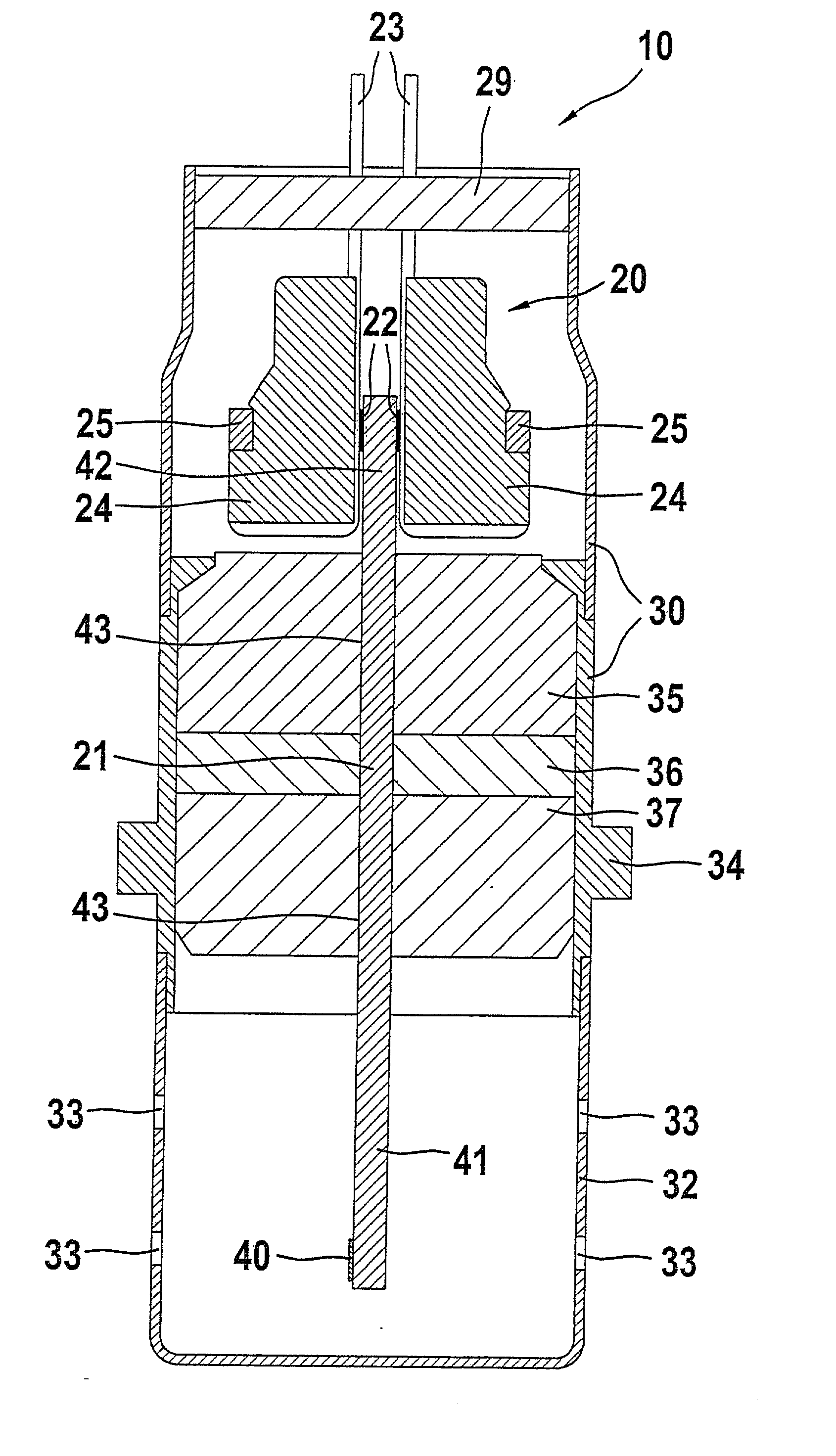
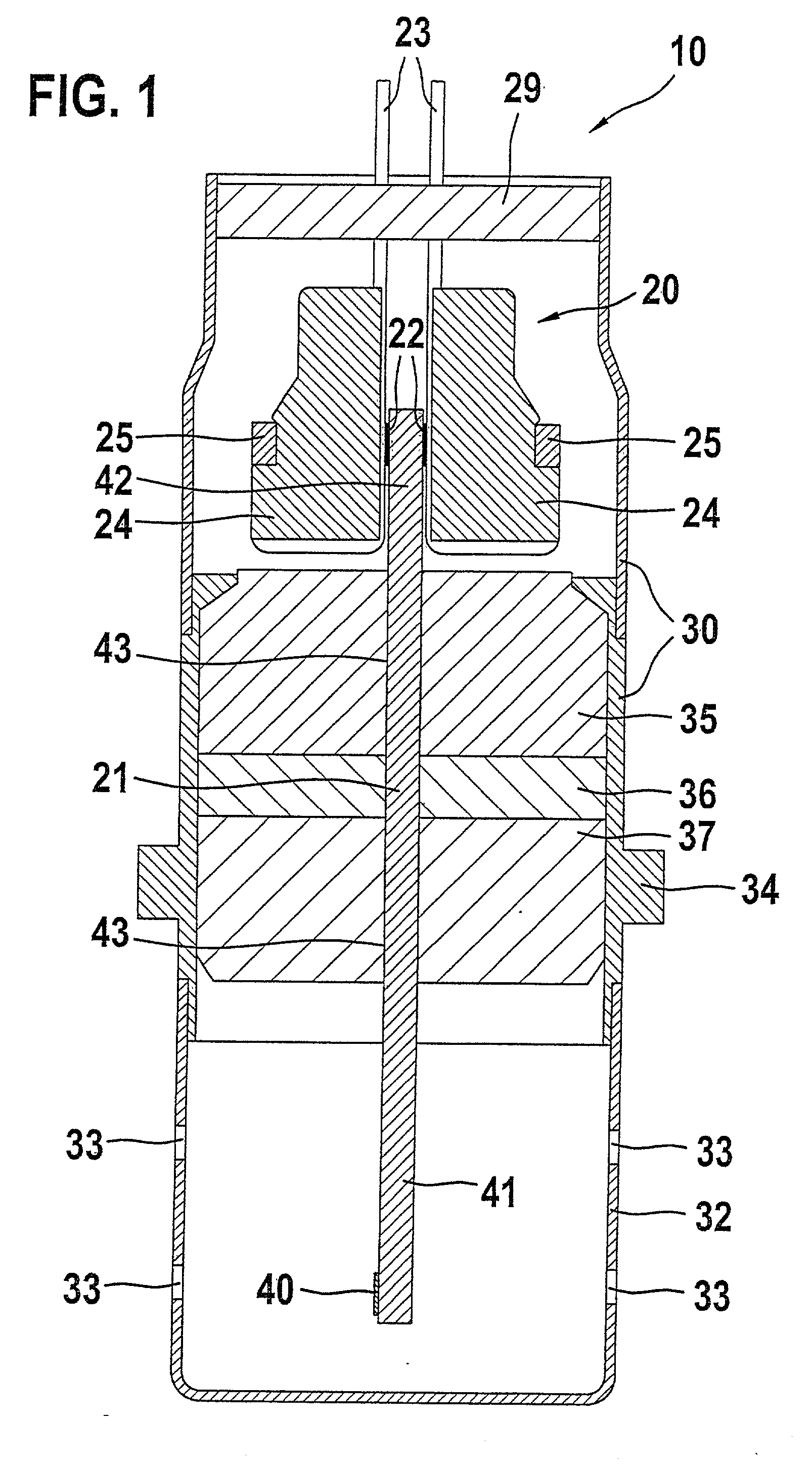
[0016] FIG. 1 shows a gas probe 10 with a metal housing 30, in which two ceramic molded parts 35, 37, one on the connection side and one on the measurement gas side, are disposed. The two ceramic molded parts 35, 37 each have an opening 43, the openings extending in alignment with one another, in which a chip-shaped sensor element 21 is located with one end portion 41 on the measurement gas side and another end portion 42 on the connection side. Between the ceramic molded parts 35, 37 on the connection and measurement gas sides, there is a sealing element 36.

[0017] The end portion 41 of the sensor element 21 on the measurement gas side protrudes out of the housing 30 and is surrounded by a protective tube 32, which is fixed to the housing 30. The gas probe 10 is secured by means of a collar 34 in a measurement opening, not shown, of a measurement gas chamber, such as an exhaust gas line of an internal combustion engine. The gas to be measured passes through inlet and outlet openings...


PUM


Abstract

The invention relates to a gas probe (10) for installation in a measurement gas chamber, having a metal housing (30) in which a planar sensor element (21) is disposed, electrically insulated, with at least one contact face (22) that is conductively connected to a metal conductor element (23). For the conductor element (23), an electrically insulating contact holder (24) is provided, which presses the conductor element (23) onto the contact face (22) by means of a spring element (25) that engages the contact holder (24). The conductor element (23) is disposed in an indentation (26) of the contact holder (24), which indentation is oriented toward the contact face (22) of the sensor element (21), and by way of a region protruding out of the indentation (26) of the contact holder (24), the conductor element is in contact with the contact face (22).

Description

PRIOR ART[0001] The invention is based on a gas probe as generically defined by the preamble to claim 1.[0002] One such gas probe is known, for instance from European Patent Disclosure EP 0506897 B1, for use in exhaust gas analysis for internal combustion engines. Such gas probes have a metal housing, in which an elongated, planar sensor element is disposed, electrically insulated, with one region on the measurement side and one region on the connection side. In the connection region, the sensor element has contact faces, which are electrically connected to a measurement point located in the measurement region. The gas probe also has a contacting device, which contains conductor elements that are in conductive contact with the contact faces of the sensor element and which extend out of the housing. By means of a spring element that engages a contact holder, the conductor elements are pressed onto the contact faces. The regions of the contact holder that contact the conductor element...

Claims


Application Information

Patent Timeline
IPC IPC(8): G01N27/409G01N27/407
CPCG01N27/4071
Inventor WEYL, HELMUTWILDE, JUERGEN
Owner ROBERT BOSCH GMBH
Why Eureka
Try Eureka