

Industrial fabric with wear resistant coating
a technology of industrial fabric and coating, which is applied in the field of corrugated fabric “top belts” and can solve the problems of irreparable damage to the fabric used in the fabrication of paper-constructed products, damage to the fabric used in the paper-constructed products, and damage to the fabric used in the machine manufacturing of paper-constructed products
Inactive Publication Date: 2011-06-23
VOITH PATENT GMBH
View PDF12 Cites 16 Cited by
- Summary
- Abstract
- Description
- Claims
- Application Information
AI Technical Summary
Benefits of technology
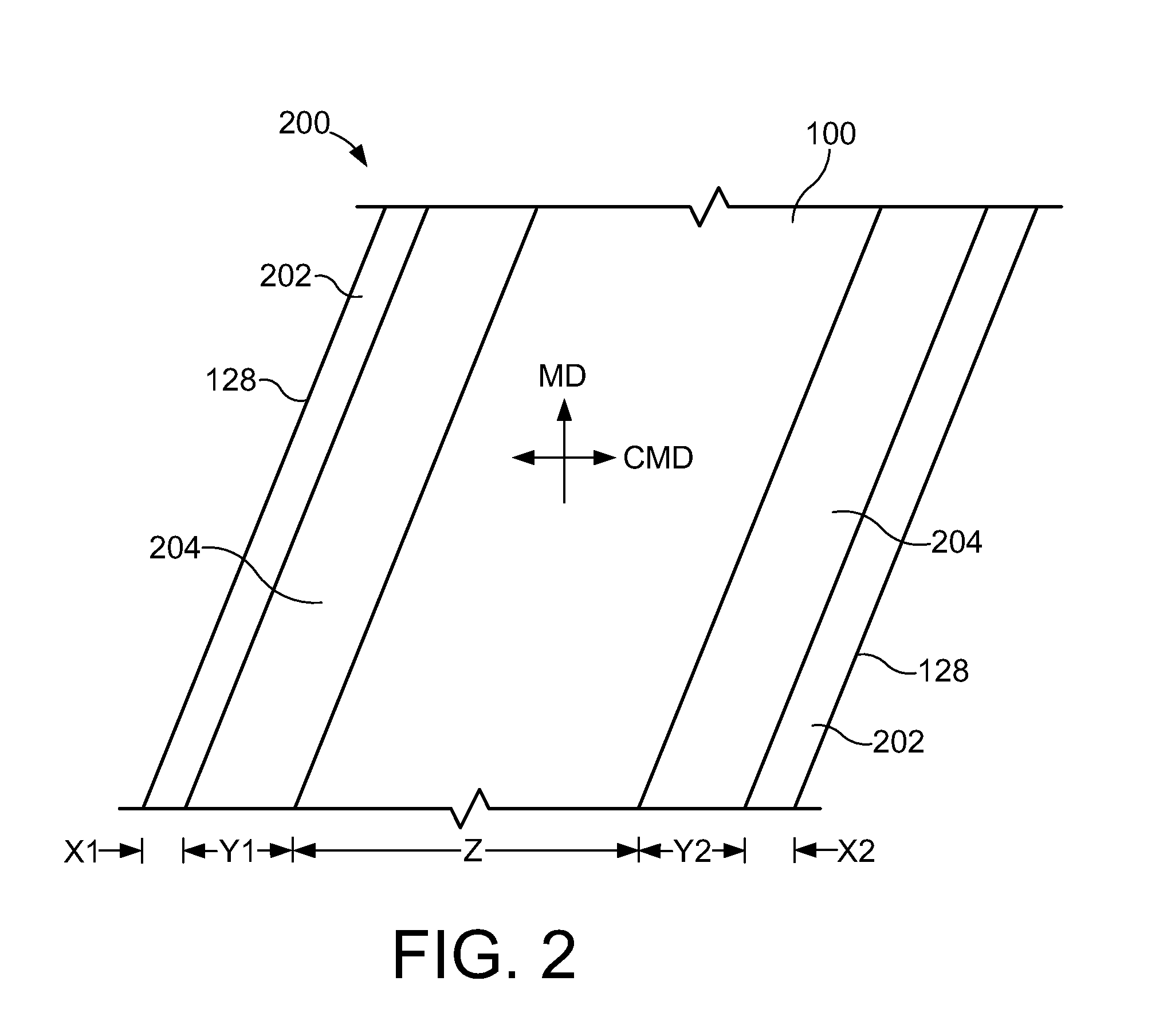
[0010]The present invention provides a fabric including a spiral base fabric wherein the fabric comprises a non-marking spiral seam integrated with the body of the fabric, i.e., the seam and the base fabric are essentially the same. The base fabric incorporates conductive yarns and the edges are coated for 1″ with conductive adhesive to complete the conductive grid. Furthermore, silicon is custom coated on the board side edges (between the 1″ conductive edges). Custom coated for the narrowest boards produced, e.g., an 88″ wide belt and a presumed narrowest board of 48″, then the coating will be 20″ on each edge (1″ for the conductive adhesive and 19″ for the silicon). The silicon coating is flush with the surface of the fabric so that it does not mark the board and is soft and supple yet hard wearing. The silicon also helps pull the board through the machine at start-ups and after board breaks.
[0011]The invention in one form is directed to a monofilament base fabric incorporating conductive yarns and conductive edging, to complete the conductive grid. This fabric can provide one or more of the following advantages: heat and hydrolysis resistant materials, providing light weight high strength fabrics, having a high permeability in the central portion of the fabric, a surface with a high coefficient of friction due to the silicon coated edges on the board side of the belt. The present invention also relates to an integrated spiral loop seam integrated with the base fabric which can provide one or more of the following advantages: be an extremely stable and yet flexible corrugator fabric, with superior heat and hydrolysis resistance and the ability to provide a non-marking loop seam, and board pulling power due to the silicon coated edges. The base fabric is a conductive spiral fabric that is coated on the board side edges of the fabric with a silicon rubber compound. This provides the high traction (high coefficient of friction) required. This characteristic is desired in a corrugator belt to pull the corrugated boxboard through the machine without any slippage. The non-marking seam is another desirable feature that this belt possesses. Further, because of the base structure, if the fabric is damaged in use then that particular damaged section can be removed and the fabric joined back together again and production is resumed relatively quickly. The conductive nature of the base fabric is required to prevent “shocking” of nearby personnel and also prevents fires that can be easily ignited in this environment with an electronic spark. This lighter weight design also requires less amperage from the drive motor which is additional energy savings. Also, the monofilament / silicon structure requires less cleaning because it repels the starch that is prevalent during the manufacture of boxboard. This is also an economic advantage over traditional belts.
[0013]In view of the description noted above, the corrugator belt of the present invention possesses certain features such as strength, durability, dimensionally stable, and has a non-marking seam under all the conditions of high temperature steam, plus high tension. Furthermore, the belts are flexible in the machine direction yet sufficiently stable in the cross machine direction so as to maintain close to the belt's original dimensions and facilitate the ability to be guided along its passage around the machine under the conditions described. More importantly, the belts are sufficiently permeable to allow the evaporation of vapor to pass easily through the material so as not to rewet the corrugated box-board. Also, a non-marking seam, of the same caliper of the base fabric is desired, as in this case. Plus, silicon coated edges are provided to protect the exposed top belt when the board is narrower than the fabric, e.g., the top belt is 88″ wide and the narrowest board produced on a particular machine is 48″ wide, then the edges will be coated with silicon for 20″ on each board side. On the very edge, conductive adhesive such as F-611 from Plastidip is applied to form the conductive grid with the conductive yarns in the center of the spirals.
[0014]However, corrugator belts exhibiting all of the above desirable features have heretofore not been available. Conventional corrugator belts exhibited low permeability and used the principle of absorption and then evaporation but problems of rewetting the corrugated box-board occurred which means the corrugator machine was restricted to speed because drying was being restricted. Moreover, these types of belts were typically heavy and very low in permeability. Or, if a more open design, i.e., higher permeability compared to traditional corrugator belts was employed, the board side edges were not protected from the wear that occurs from the exposed fabric to the hot plates and dried glue / starch that makes a sandpaper-like environment which leads to premature wear removal or poor edge bonding because the caliper of the fabric at the edges is smaller than the central portion of the fabric.
Problems solved by technology
An ESD can not only damage the paper constructed product in production, but also irreparably damage the fabric used in the fabrication of the paper constructed product.
This can lead to costly replacement of the fabric and down time for the manufacturing apparatus.
In the worst case scenario, the machine fabricating the paper constructed product can be damaged, or initiation of a fire could result.
These metal hooks are not an integral part of the corrugator belt and this can create several problems.
The biggest problem can be marking of the boxboard being produced especially on boxboard constructed with e-flute or finer corrugating medium.
This marking causes considerable waste and / or subsequent printing problems.
Other problems caused by the metal hooks can be the fracture of the clipper hooks and mechanical wear and the subsequent damage to the corrugator machine components resulting from the clipper hooks themselves.
Because these materials are so dense they are consequently very low in permeability which prevents steam vapor from passing through the corrugator belt material.
This, in turn slows down the bonding process and therefore the speed of the corrugator machine.
These metal hooks are not an integral part of the corrugator belt and therefore need to be covered with a flap or fibers and this can create several problems.
The biggest problem can be marking of the boxboard being produced especially on boxboard constructed with e-flute or finer corrugating medium.
Method used
View moreImage
Smart ImageViewing Examples

Examples
example 1
[0039]A fabric was manufactured for a corrugator machine and was constructed using a 0.90 mm diameter polyester spiral and 0.90 mm diameter hinge pin. It was stretched and heat set at 48 pli and 210° C. After that it was measured, electrostatic control yarns of 0.52 mm diameter (nylon impregnated with carbon) were inserted into the spirals. Then cut to finished size for the customer's corrugator machine and then edge coated for 1″ with conductive carbon impregnated synthetic rubber. The board side edges were then coated with liquid rubber compound on the board side of the fabric for a total of 20″ in total from each edge (19″ silicon, 1″ of conductive adhesive). The silicon rubber compound was then heat cured at 175° C. at 48 pli.
Login to View More PUM
| Property | Measurement | Unit |
|---|---|---|
| thickness | aaaaa | aaaaa |
| tear strength | aaaaa | aaaaa |
| operating temperature | aaaaa | aaaaa |
Abstract
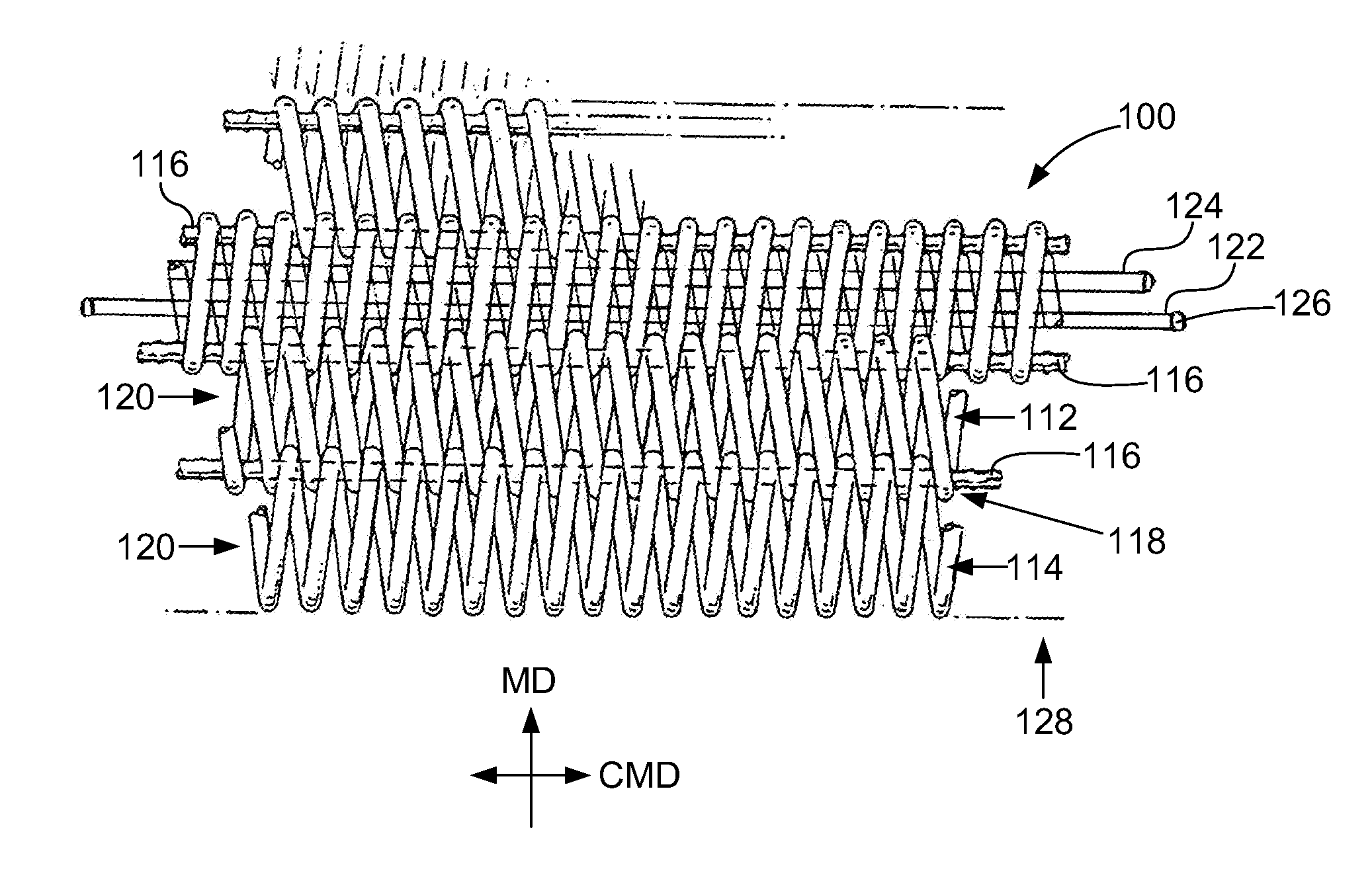
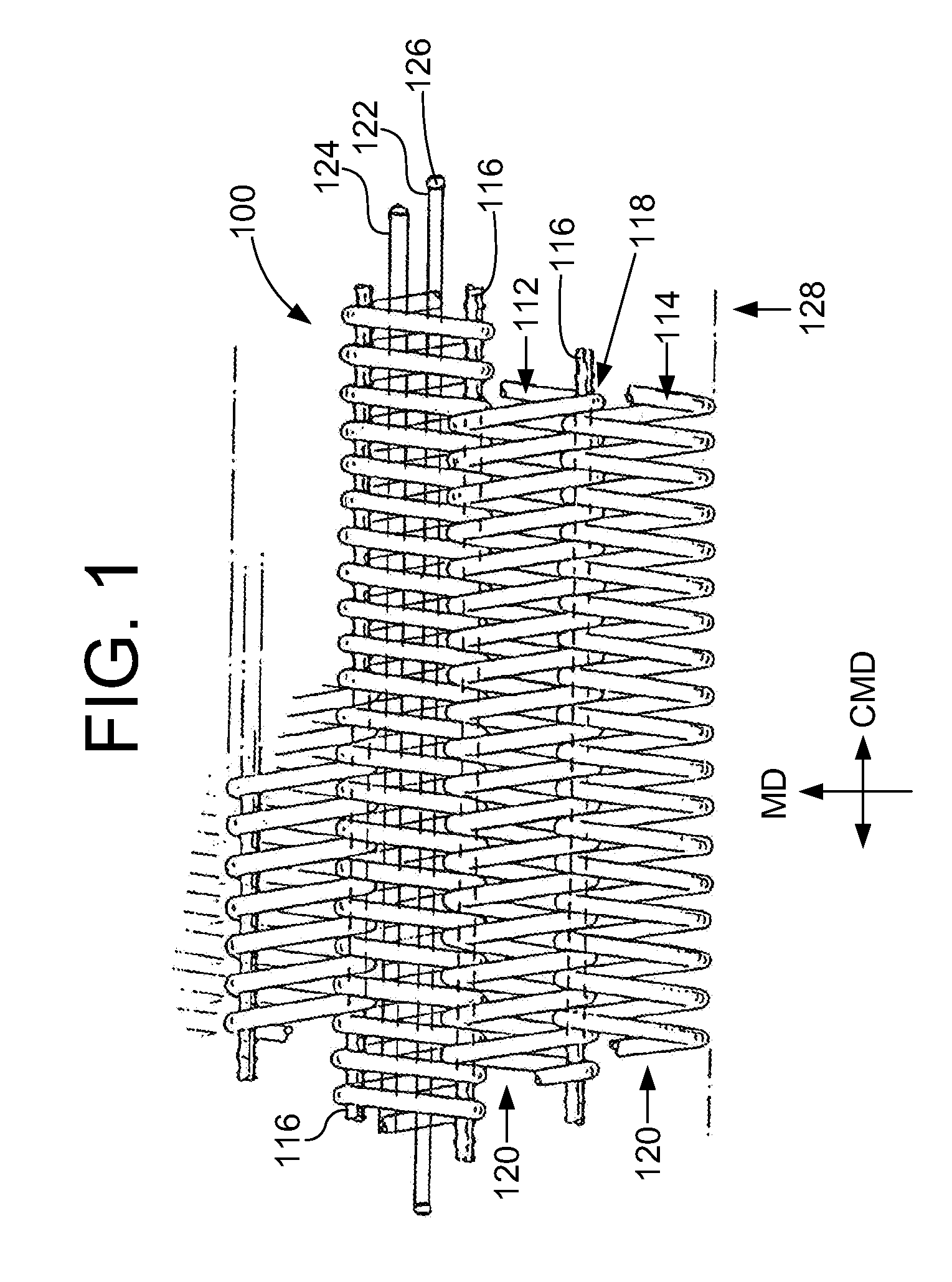
An industrial fabric used in the manufacture or processing of at least one material web includes a base fabric having a board side and a machine side. The base fabric includes a plurality of spirals extending in a cross machine direction (CMD). The spirals are interconnected together with each other along adjacent peripheral edges to form a spiral link fabric. The base fabric has opposite lateral side edges extending in a machine direction (MD). One or more electrostatic control yarns are positioned within a corresponding spiral and extend in the CMD direction to the lateral side edges. A pair of conductive edge coatings are applied to at least the board side of a respective lateral side edge for a predetermined width. The conductive edge coatings and the one or more electrostatic control yarns form an electrostatic grid. A pair of wear resistant coatings are applied to an area adjacent a respective conductive edge coating such that a substantially constant spacing between the wear resistant coatings corresponds to a minimum expected working width of the industrial fabric. The wear resistant coatings are wear resistant with a hardness of between approximately 50 to 66 Shore A Durometer Hardness, and a coefficient of friction greater than approximately 2 on the board side. The industrial fabric has a completely non-marking seam because of its integral nature with the base fabric and the equal amount of the wear resistant coating at the seam and the edges.
Description
BACKGROUND OF THE INVENTION[0001]1. Field of the Invention[0002]The present invention relates to papermaking, and relates more specifically to corrugator “top belt” fabrics employed in making corrugated paper board, or box-board on a double-backer boxboard machine.[0003]2. Description of the Related Art[0004]During the fabrication and use of most fabrics manufactured with monofilament yarns, static electricity can build-up. The result of static electricity build-up is the occasional spontaneous electrostatic discharge (ESD). An ESD can not only damage the paper constructed product in production, but also irreparably damage the fabric used in the fabrication of the paper constructed product. This can lead to costly replacement of the fabric and down time for the manufacturing apparatus. In the worst case scenario, the machine fabricating the paper constructed product can be damaged, or initiation of a fire could result.[0005]An example of a paper constructed product is corrugated box...
Claims
Login to View More Application Information
Patent Timeline
 Patent Type & AuthorityApplications(United States)
IPC IPC(8): B32B37/00B32B3/10B32B3/02
CPCD21F1/0036Y10T428/2476D21F1/0072
InventorHARWOOD, WILLIAM
OwnerVOITH PATENT GMBH