Control method and control system of redox flow battery and redox flow battery

A technology of liquid flow batteries and electric stacks, which is applied in the direction of fuel cells, regenerative fuel cells, circuits, etc., and can solve the problems that flow batteries cannot be realized, SOC detection results are inaccurate, and the efficiency of flow batteries is reduced.

Active Publication Date: 2017-09-22
DALIAN RONGKE POWER
View PDF3 Cites 8 Cited by
  • Summary
  • Abstract
  • Description
  • Claims
  • Application Information

AI Technical Summary

Problems solved by technology

The SOC detection method of the flow battery in the prior art only considers the SOC of the electrolyte at the inlet or outlet of the stack, and does not comprehensively consider the SOC of all the electrolytes in the electrolyte storage tank, resulting in inaccurate SOC detection results and insufficient Reflect the actual state of charge of the flow battery
[0005] 2. There are many operating state parameters of the flow battery. At present, the electrolyte flow control of the flow battery is relatively simple, and the circulating pump is only controlled according to the output power demand, without considering different electrolyte temperatures, SOC, capacity decay rates and charging conditions. The difference in discharge power to the demand for electrolyte reactants makes it impossible for the flow battery to intelligently regulate the electrolyte flow with reference to various operating state parameters, resulting in increased power consumption of the circulating pump and reduced efficiency of the flow battery
[0006] 3. When charging the flow battery, the charging cut-off condition is

Method used


Image

  • Control method and control system of redox flow battery and redox flow battery
  • Control method and control system of redox flow battery and redox flow battery
  • Control method and control system of redox flow battery and redox flow battery

Examples


Embodiment Construction

[0106] In order to make the purpose, technical solutions and advantages of the embodiments of the present invention clearer, the technical solutions in the embodiments of the present invention will be clearly and completely described below in conjunction with the drawings in the embodiments of the present invention. Obviously, the described embodiments It is a part of embodiments of the present invention, but not all embodiments. Based on the embodiments of the present invention, all other embodiments obtained by persons of ordinary skill in the art without creative efforts fall within the protection scope of the present invention.

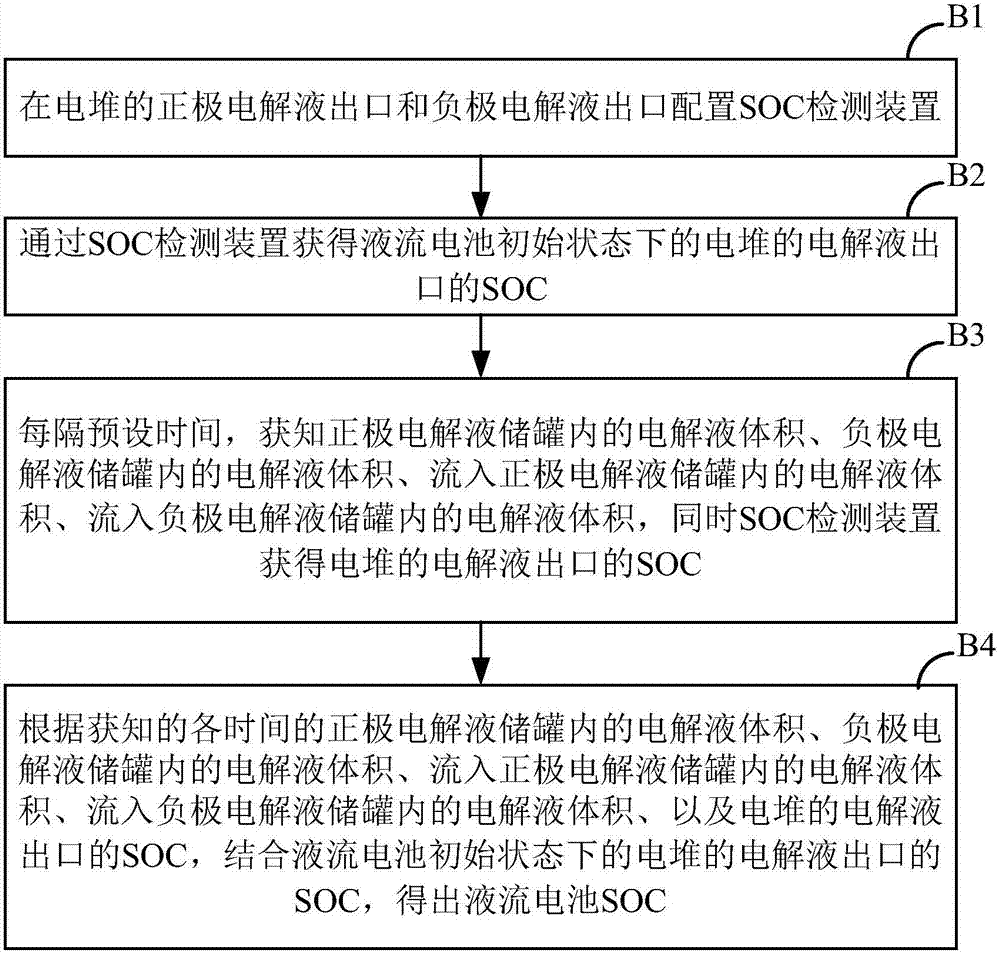
[0107] Such as figure 1 As shown, a liquid flow battery control method includes the following steps:

[0108] Step B1: configure SOC detection devices at the positive electrolyte outlet and the negative electrolyte outlet of the stack;

[0109] Step B2: Obtain the SOC of the electrolyte outlet of the stack in the initial state of the flow batter...


PUM


Abstract

The invention discloses a control method and control system of a redox flow battery and the redox flow battery. The control method comprises the following steps of configuring SOC detection devices at a positive electrolyte outlet and a negative electrolyte outlet of an electric stack; acquiring SOC of the electrolyte outlets of the electric stack under an initial state of the redox flow battery by the SOC detection devices; acquiring electrolyte volume in a positive electrolyte storage tank, electrolyte volume in a negative electrolyte storage tank, electrolyte volume flowing into the positive electrolyte storage tank and electrolyte volume flowing into the negative electrolyte storage tank per preset time, and simultaneously acquiring the SOC of the electrolyte outlets of the electric stack by the SOC detection devices; and obtaining SOC of the redox flow battery. SOC detection results in the positive electrolyte storage tank and the negative electrolyte storage tank within a certain time are accumulated and averaged, so that the SOC detection results are more accurate.

Description

technical field [0001] The invention belongs to the technical field of liquid flow batteries, and specifically relates to a liquid flow battery control method and control system thereof, and a liquid flow battery. Background technique [0002] Liquid flow battery has the advantages of flexible design (power and capacity can be independently designed), long service life, good charge and discharge performance, free site selection, high energy efficiency, safety and environmental protection, low maintenance cost, and easy realization of large-scale storage. Many advantages not available. In practical applications, liquid flow batteries can be widely used in renewable energy power generation systems such as wind energy and solar energy as energy storage systems, so that the generated electricity can be output continuously and stably; The power in low valleys is stored and output during peak power consumption to balance power supply and demand; in addition, it can also be used a...

Claims


Application Information

Patent Timeline
IPC IPC(8): H01M8/18H01M8/0438H01M8/04746
CPCH01M8/0438H01M8/04753H01M8/188Y02E60/50
Inventor 叱干婷张华民马相坤吴静波吕善强陈宁
Owner DALIAN RONGKE POWER
Why Eureka
Try Eureka