Cytometer

a flow cytometer and cytometer technology, applied in the field of flow cytometers, can solve the problems of affecting the overall performance of the system, the complexity of the optical system, the increase of the dimension of the structure, and the error of cell analysis, so as to achieve the effect of reducing the number of side lobes

Active Publication Date: 2008-06-10
SHENZHEN MINDRAY BIO MEDICAL ELECTRONICS CO LTD
View PDF7 Cites 43 Cited by
  • Summary
  • Abstract
  • Description
  • Claims
  • Application Information

AI Technical Summary

Benefits of technology

[0031]The advantage of the present invention is as follows. In the present invention, while achieving light beam shaping with a pair of mutually crossing cylindrical lenses, an aspheric lens with a large numerical aperture (e.g., 0.3-0.5) is used for collimating the light beam with a large scattering angle. Thereby, the present invention eliminates the side lobes of the irradiating spot at the cell-interrogation zone of the flow chamber by way of the optical system and avoids the disturbance of the false pulse of the scattered signal to the light beam path, which renders the result of the detection more accurate. The realization of such accuracy is ensured by the design of the optical system and is an intrinsic feature, without signal processing needed for the related eliminating process, so that signal processing becomes simpler and more direct, providing the present invention with improved practicability.
[0032]The collimating lens of the present invention takes the form of an aspheric collimating lens, and the lens surface thereof satisfies the following formula:
[0034]Such an aspheric collimating lens guarantees the acquisition of a large numerical aperture, so that the elimination of the side lobes of the irradiating spot is ensured.
[0035]Additionally, the present invention uses a semiconductor laser, so that the structural dimension of the instrument system is significantly reduced.

Problems solved by technology

However, this approach has a significant disadvantage in that usually the main pulse Pk of some smaller cells is even smaller than the associated pulse of the bigger cells, and the real scattered signal Pk of the small cells would be rejected along with the associated pulse of the bigger cells by using the threshold value, which will bring error to the cell analysis.
However, this approach has the following drawbacks: the complexity of the optical system, the dimension of the structure, and the difficulties upon assembly and adjustment are all increased; while minimizing the error in y direction, the concave cylindrical lens also influences the x direction, as a result of which the flat top effect upon light beam shaping is poor, which further affects the overall performance of the system; for certain systems requiring irradiation with multi-wavelength, the compensation effect of such a concave cylindrical lens is inconsistent, and it is still needed to increase the complexity of the signal recognition algorithm.
Although this approach also functions to eliminate the sidelobs, the application of the space filter enlarges the size of the structure and increases the difficulty upon assembly and adjustment.
Furthermore, one spherical lens is incapable of forming a flat top in x direction, leading to aberration if the cells are introduced into the irradiated region from different positions.

Method used


Image

  • Cytometer
  • Cytometer
  • Cytometer

Examples


Embodiment Construction

[0049]The invention is described in greater details below with reference to the accompanying drawings and the illustrative embodiments.

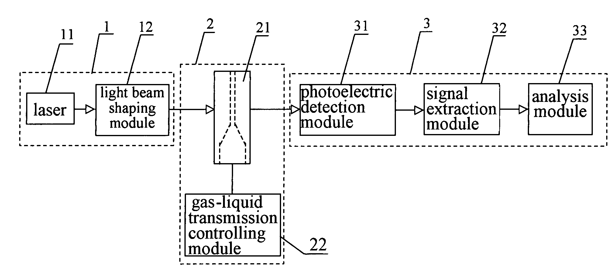
[0050]Referring to FIGS. 4-12, the cytometer according to the present invention comprises an illuminating unit 1, a sample generation unit 2 and a signal processing unit 3 which are connected in series.

[0051]The illuminating unit I comprises a laser 11 and a light beam shaping module 12, as shown in FIG. 4.

[0052]The light beam shaping module 12 is used for collimating and shaping the laser light beam emitted from the laser 11. As shown in FIG. 6, the module 12 comprises a piece of aspheric collimating lens 121 and a pair of mutually crossing cylindrical lens 122 and 123 functional as outputting a light beam with an elliptical cross section which irradiates onto the cells flowing within the flow chamber 21. The length of the minor axis of the ellipse is about 15 μm-25 μm and that of the major axis is about 160 μm-220 μm, and moreover the distribution ...


PUM

PropertyMeasurementUnit
depthaaaaaaaaaa
depthaaaaaaaaaa
depthaaaaaaaaaa

Abstract

A cytometer includes an illuminating unit having a laser and a light beam shaping module for shaping and converging the laser beam emitted from the laser. A sample generation unit includes a gas-liquid transmission controlling module and a flow chamber which are connected to each other, so the sample liquid containing the cells to be detected may flow through the flow chamber while being encircled by the sheath fluid. A signal processing unit receives, converts and processes the scattering light emitted from the flow chamber. The signal processing unit includes at least a photoelectric detection module, wherein the light beam shaping module has at least one aspheric collimating lens and a pair of mutually crossing cylindrical lenses, and the numerical aperture of the aspheric collimating lens is at least 0.3.

Description

STATEMENT OF RELATED APPLICATION[0001]This application claims the benefit of priority to China Patent Appl. No.: 200610020150.4, filed Jan. 9, 2006, entitled “Cytometer”.FIELD OF THE INVENTION[0002]The present invention relates to a flow cytometer, in particular, to a blood cell cytometer.BACKGROUND OF THE INVENTION[0003]Conventional flow cytometers have been widely used in the analysis of blood cells. Such a blood cell cytometer is mainly comprised of an illuminating unit, a flow chamber and a signal processing unit. The flow chamber provides an optical cell-interrogation zone, in which a flow of the sample of blood cells is encircled in a sheath flow according to the fluid focusing principle, so that the blood cells pass through the detection passage one by one; the illuminating unit, usually a laser, provides an illuminating light beam which may irradiate into the cell-interrogation zone of the flow chamber, such that the illuminating light beam may irradiate onto the cells flowi...

Claims


Application Information

Patent Timeline
Patent Type & Authority Patents(United States)
IPC IPC(8): G01N21/00
CPCG01N15/1459G01N15/1434G01N2015/1486
Inventor CHU, JIANJUNLI, YINGCHUN
Owner SHENZHEN MINDRAY BIO MEDICAL ELECTRONICS CO LTD
Why Eureka
Try Eureka