Coupling device of jig

a technology of coupling device and jig, which is applied in the field of jigs, can solve problems such as affecting and achieve the effect of ensuring the processing accuracy of workpieces

Inactive Publication Date: 2017-06-06
CHERNG JIN TECH
View PDF10 Cites 5 Cited by
  • Summary
  • Abstract
  • Description
  • Claims
  • Application Information

AI Technical Summary

Benefits of technology

[0007]In view of the above, the primary objective of the present invention is to provide a coupling device, which ensures the processing accuracy of workpieces.
[0009]Since the area where the abutment surface of the piston base abuts against each ball is not merely a single point, the force applied on the abutment surface can be dispersed to prevent the abutment surface from being damaged, and therefore the processing accuracy of workpieces under processing can be ensured.

Problems solved by technology

As a result, the surface of the inclined section 164 tends to dent, which leads to slight mismatch between the coupling device 1 and the jig 18, and thus affects the processing accuracy of the workpieces.

Method used


Image

  • Coupling device of jig
  • Coupling device of jig
  • Coupling device of jig

Examples


Embodiment Construction

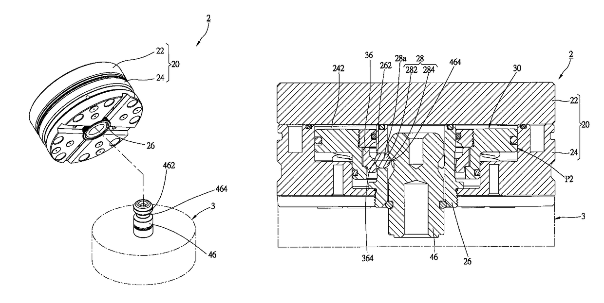
[0023]As shown in FIG. 3 to FIG. 7, a coupling device 2 of the first preferred embodiment of the present invention includes a foundation 20, a tube 26, a plurality of balls 28, and a piston base 30. The coupling device 2 is coupled to a jig 3, which includes a plug 46, and the plug 46 has a head 462 and a neck 464.

[0024]The foundation 20 has a top seat 22 and a bottom seat 24 connected to the top seat 22, wherein the top seat 22 is used for placing workpieces (not shown), and the bottom seat 24 touches a surface of the jig 3. The bottom seat 24 has a chamber 242 and a perforation 244 which connects the chamber 242 to an exterior of the foundation 20.

[0025]An end of the tube 26 is inserted into the perforation 244 of the bottom seat 24 to enter the chamber 242. More specifically, a part of the tube 26 is inside the chamber 242, and the rest is inside the perforation 244. The tube 26 has an outer screw thread adjacent to a distal end thereof, and the perforation 244 has a correspondin...


PUM


Abstract

A coupling device of jigs includes a foundation, a tube, a plurality of balls, and a piston base. The foundation has a chamber, in which a part of the tube is inserted. The tube has a plurality of through holes for housing the balls. The piston base is received in the chamber, and fitted to the tube. An inner surface of the piston base has a circular groove and an abutment surface. The piston base can be moved along an axial direction of the tube between a first position and a second position. When at the first position, a part of each ball is inside the circular groove; when at the second position, an area where the abutment surface abuts against each ball is not merely a single point. Whereby, the force applied on the abutment surface is dispersed, and therefore the processing accuracy of workpieces is ensured.

Description

BACKGROUND OF THE INVENTION[0001]1. Technical Field[0002]The present invention relates generally to jigs, and more particularly to a coupling device of a jig.[0003]2. Description of Related Art[0004]Jigs are used to repeatedly and accurately produce great amount of products, and there are various types of jigs compatible for different processing methods and different usages. For example, a jig applied for electrical discharge machining (EDM) is usually placed in an EDM machine which is connected to a power source. A metal workpiece is engaged to a coupling device, and the coupling device is coupled with a jig to process the workpiece. Therefore, the coupling device can be conveniently decoupled from the jig with the workpiece still engaged thereto.[0005]As shown in FIG. 1, a conventional coupling device 1 includes a foundation 10, a tube 12, a plurality of balls 14, and a piston base 16. Metal workpieces are placed on the foundation 10, wherein the foundation 10 has a chamber 102 wi...

Claims


Application Information

Patent Timeline
Patent Type & Authority Patents(United States)
IPC IPC(8): B23B31/107B23Q1/00B23B31/30B23B31/22
CPCB23B31/1071B23Q1/0072B23B31/107B23B31/22B23B31/30Y10T279/1291Y10T279/17743Y10T279/17752Y10T279/17811
Inventor LIN, CHIEN-CHIH
Owner CHERNG JIN TECH
Why Eureka
Try Eureka