Press-forming die for glass elements

Inactive Publication Date: 2002-03-12
NGK INSULATORS LTD +1
View PDF13 Cites 4 Cited by
  • Summary
  • Abstract
  • Description
  • Claims
  • Application Information

AI Technical Summary

Benefits of technology

The die constructed as described above makes it possible to perform the press-forming operation in which the die release performance is excellent without any adhesion or deposition of softened glass material onto the die, even in the case of the use of any one of various glass materials selected depending on the use or application of the glass element, including, for example, crystalline glass materials (non-crystalline materials), chemically tempered glass materials (materials before the ion exchange treatment), and 
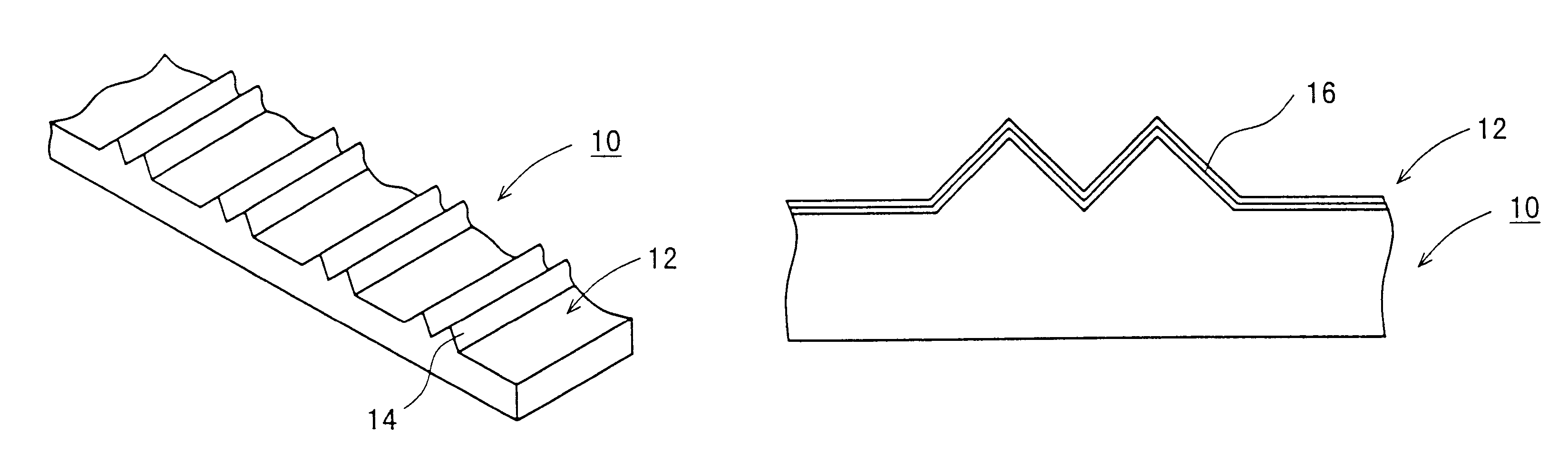
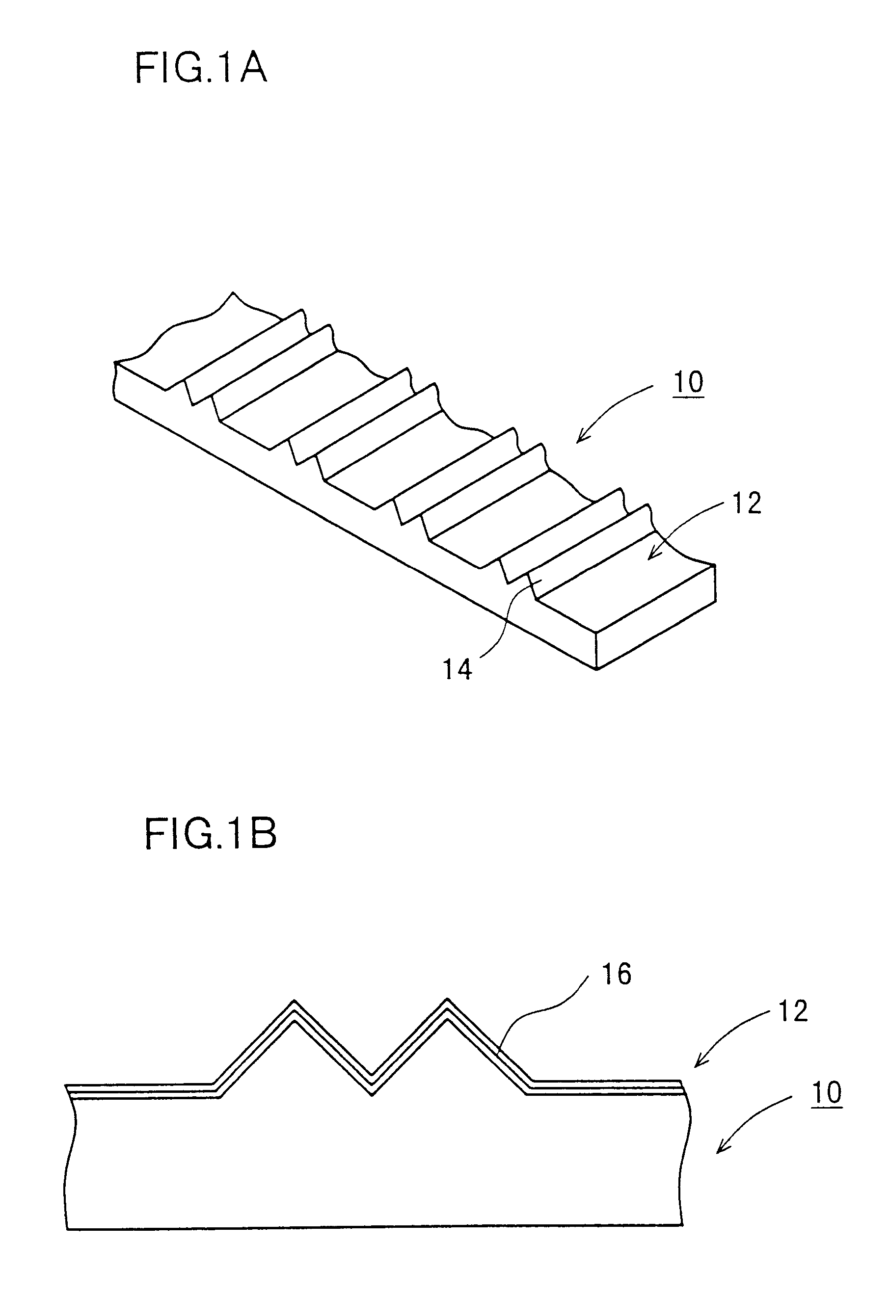
borosilicate glass. Further, V-shaped grooves are formed on the glass substrate as the material for the glass element, and an optical fiber is arranged in the grooves by using an adhesive. Therefore, the adhesive performance is excellent for the optical fiber to be glued to the glass substrate.
In the present invention, the glass element for optical IC, which belongs to the glass element, is not necessarily subjected to precision 
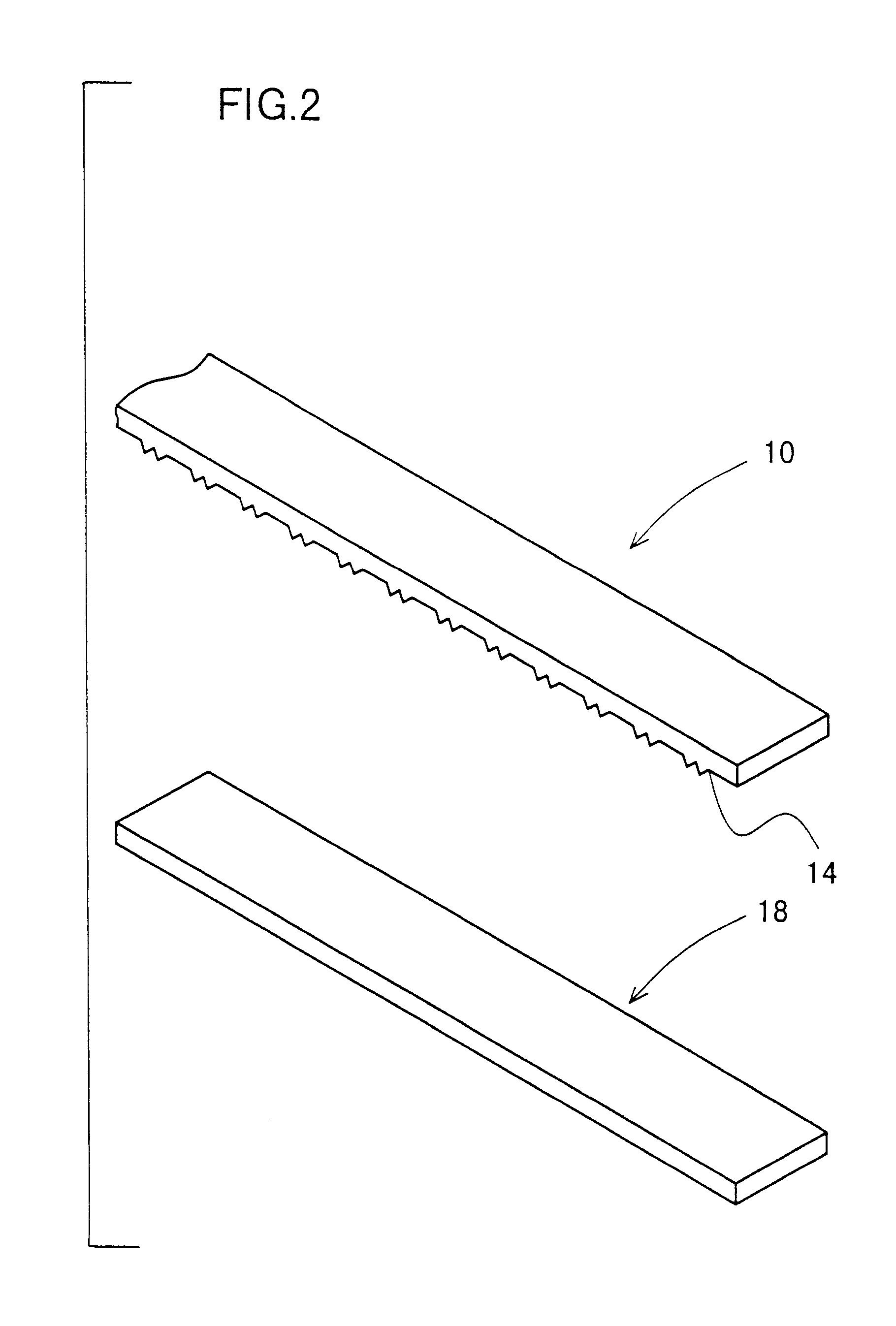
machining into one having an extremely small degree of surface roughness. Especially, for example, when the predetermined grooves for embedding the optical fiber are provided by means of the press-forming on a connector part for optically coupling the optical fiber and the IC chip, it is sufficient to give a processing accuracy in such a degree that the optical fiber can be positioned at a submicron level.
An allowable value in view of the positioning accuracy for the optical fiber (single mode), i.e., an upper limit value of the surface roughness of the glass element is preferably not more than 1.2 .mu.m as represented by Rmax, more desirably not more than 1.0 .mu.m. On the other hand, from a viewpoint to improve the adhesive performance for the glass fiber to be glued to the glass substrate, it is preferable to increase the adhesion area by providing a certain degree of surface roughness. A lower limit value of the surface roughness of the glass element is preferably not less than 0.4 .mu.m as represented by Rmax, more desirably not less than 0.5 .mu.m.
The press-forming die according to the present invention is excellent in die release performance. The die is also excellent in adhesive performance for the optical fiber adhered to the glass substrate by the aid of an adhesive, and the die is sufficient to ensure the processing accuracy as described above. The press-forming die according to the present invention is more preferably used for such use or application.
The use of the forming die according to the present invention provides the forming technique in which the die release performance is extremely excellent regardless of the type of the glass material, especially when a glass material having a high softening point is used. The phenomenon of the surface oxidation of the forming die is conspicuous in the case of the conventional material such as a Pt--Ir alloy. Even when the forming operation is performed in a nitrogen gas atmosphere as a means to avoid the oxidation, it is difficult to completely dissolve the drawback, because the nitrogen gas itself to be used contains oxygen gas in a degree of 10 ppm. On the contrary, the use of the press-forming die according to the present invention, in which the Pt thin film that is relatively difficult to be oxidized is formed on the outermost surface of the press face, makes it possible to preferably perform the press-forming operation even in the nitrogen gas atmosphere.

Problems solved by technology

In general, such a method raises several issues including, for example, the die release performance between the glass element and the forming die after the forming process, the surface roughness of the glass element, and the surface quality such as whether or not any scratch exists.
Further, the material for the die raises several issues including the deterioration of die release performance resulting from the reactivity with glass during the forming process at a high temperature, and the surface scratch on the glass-pressing surface.
However, the surface roughness of this degree is within the allowable range when the product is used for the glass element for optical IC.
For this reason, a tendency is observed, in which the die release performance is deteriorated resulting from the reactivity between the forming die and the glass material and the surface oxidation of the forming die.
Even when the forming operation is performed in a nitrogen gas atmosphere as a means to avoid the oxidation, it is difficult to completely dissolve the drawback, because the nitrogen gas itself to be used contains oxygen gas in a degree of 10 ppm.

Method used


Image

  • Press-forming die for glass elements
  • Press-forming die for glass elements
  • Press-forming die for glass elements

Examples


Embodiment Construction

, a die 10 is prepared, in which a platinum film having a thickness of 0.2 .mu.m is stacked (total film thickness: 0.20 .mu.m). In Example 2, a die 10 is prepared, in which a nickel thin film having a thickness of 0.05 .mu.m is stacked beforehand, and a platinum film having a thickness of 0.2 .mu.m is stacked thereon (total film thickness: 0.25 .mu.m).

Similarly, in Example 3, a die 10 is prepared, in which a nickel thin film having a thickness of 0.05 .mu.m, a platinum-iridium alloy thin film having a thickness of 0.2 .mu.m (platinum content: 40% by weight, iridium content: 60% by weight), and a platinum thin film having a thickness of 0.2 .mu.m are stacked in this order on the base material surface (total film thickness: 0.45 .mu.m).

In Example 4, a die 10 is prepared, in which a nickel thin film having.a thickness of 0.1 .mu.m, a platinum-iridium alloy thin film having a thickness of 1.45 .mu.m (platinum content: 40% by weight, iridium content: 60% by weight), and a platinum thin f...


PUM

PropertyMeasurementUnit
Percent by massaaaaaaaaaa
Angleaaaaaaaaaa

Abstract

A platinum thin film having a thickness of 0.01 to 5 mum is formed by means of the sputtering method on a press face of a die based on the use of a cemented carbide base material. A nickel thin film having a thickness of 0.05 to 0.5 mum and a thin film made of an alloy of platinum and iridium are allowed to intervene between the cemented carbide base material and the platinum thin film, if necessary. Alternatively, an alloy thin film having a thickness of 0.01 to 5 mum, which contains 10 to 70% by weight of iridium and 30 to 90% by weight of one or more species of metals selected from metals of the platinum group except for iridium, may be allowed to intervene between the cemented carbide base material and the platinum thin film.

Description

1. Field of the InventionThe present invention relates to a press-forming die for glass elements. In particular, the present invention relates to a die for press-forming glass elements, which makes it possible to form and process glass elements for an optical IC with excellent die release performance.2. Description of the Related ArtA method for press-forming glass elements by means of a press-forming process has been hitherto used. In general, such a method raises several issues including, for example, the die release performance between the glass element and the forming die after the forming process, the surface roughness of the glass element, and the surface quality such as whether or not any scratch exists. Various countermeasures have been investigated, including, for example, the forming condition and the selection of the material for the forming die.Highly accurate forming operation is required especially when an optical lens is produced. Further, the material for the die rai...

Claims


Application Information

Patent Timeline
IPC IPC(8): C03B11/06C03B11/08C03B40/02C03B11/00
CPCC03B11/082C03B11/086C03B2215/12C03B2215/413C03B2215/32C03B2215/412C03B2215/17
Inventor OTA, TAKASHIFUKUYAMA, MASASHIHASEGAWA, HITOSHITOHYAMA, KAZUTOSHI
Owner NGK INSULATORS LTD
Why Eureka
Try Eureka