
Ultrasonic flow switch

a technology of ultrasonic flow switch and switch body, which is applied in the direction of volume/mass flow measurement, measurement device, instruments, etc., can solve the problems of difficult adjustment of sensor sensitivity, damage of ultrasonic wave emitting surface, and inaccurate determination of ultrasonic wave radiation surface of sensor, etc., to achieve easy connection and observe the display part.

Active Publication Date: 2017-06-06
KEYENCE
View PDF12 Cites 4 Cited by
  • Summary
  • Abstract
  • Description
  • Claims
  • Application Information

AI Technical Summary

Benefits of technology

[0014]Accordingly, even in the case where the element holder is mounted on pipes having various sizes, it is not necessary to bring the element holder into contact with the pipe with an excessively large force and hence, the position of an ultrasonic wave emitting portion can be accurately determined without damaging the element holder. With such accurate determination of the position of the ultrasonic wave emitting portion, reception sensitivity of an ultrasonic wave can be easily adjusted to a desired value. As a result, the ultrasonic flow switch can be stably mounted on pipes having various sizes.
[0040](15) The ultrasonic flow switch may further include a connecting part to which a connecting line for transmitting the ON / OFF signal outputted from an output part is connectable, wherein the connecting part may be provided to the element holder such that the connecting line is connectable to the connecting part from the common direction. In this case, the connecting line can be easily connected to the connecting part without causing interference with the pipe.

Problems solved by technology

However, in an actual ultrasonic flow switch, even when a sensor is fixed to a pipe having a size larger than the distance between the two sleigh-like blades, the position of an ultrasonic wave radiation surface of the sensor is not accurately determined.
Accordingly, it is difficult to adjust sensitivity of the sensor.
Further, when the sensor is fastened by a fastening band with an excessively large strength for stabilizing the position of the ultrasonic wave emitting surface, the ultrasonic wave emitting surface may be damaged.

Method used


Image

  • Ultrasonic flow switch
  • Ultrasonic flow switch
  • Ultrasonic flow switch

Examples


Embodiment Construction

[0088][1] Schematic Configuration of Ultrasonic Flow Switch

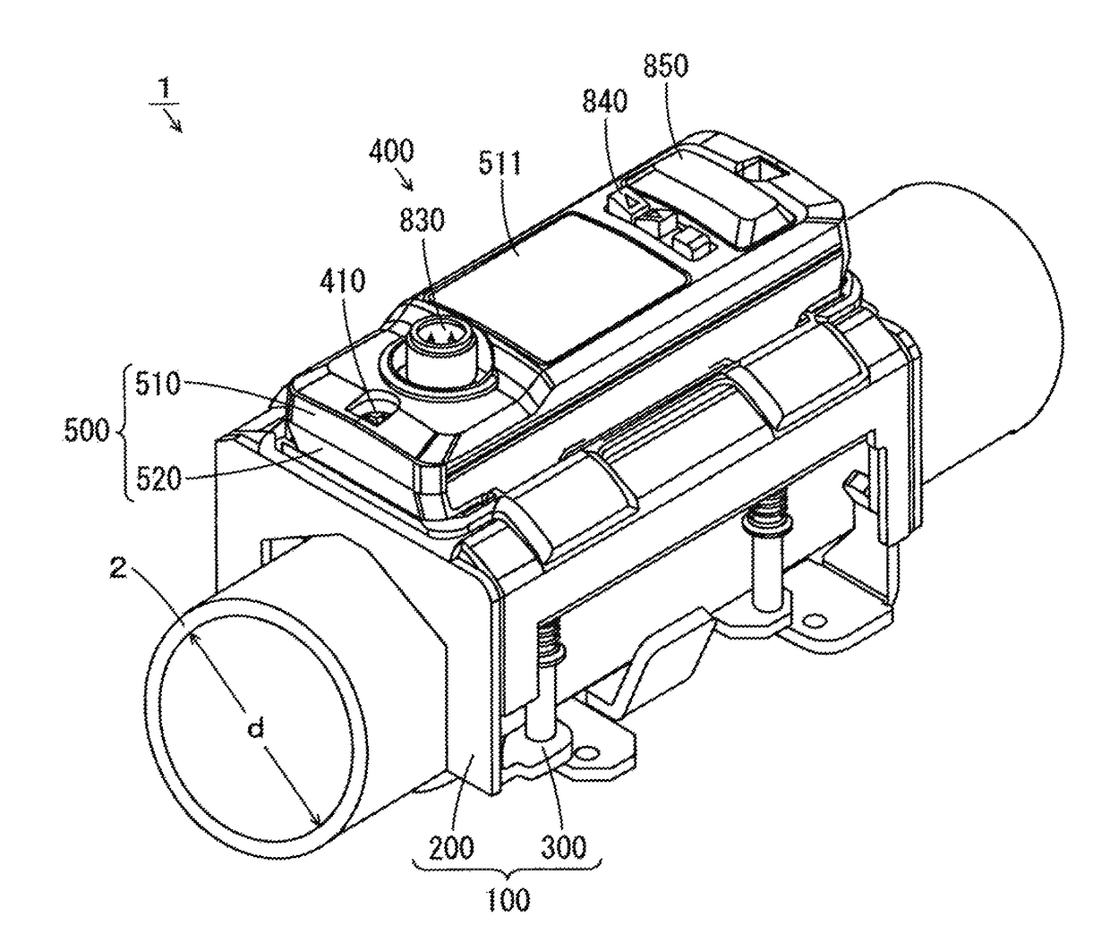
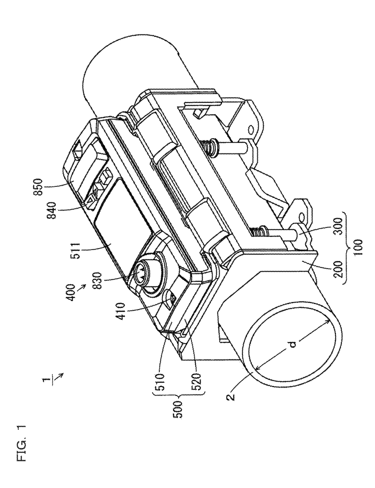
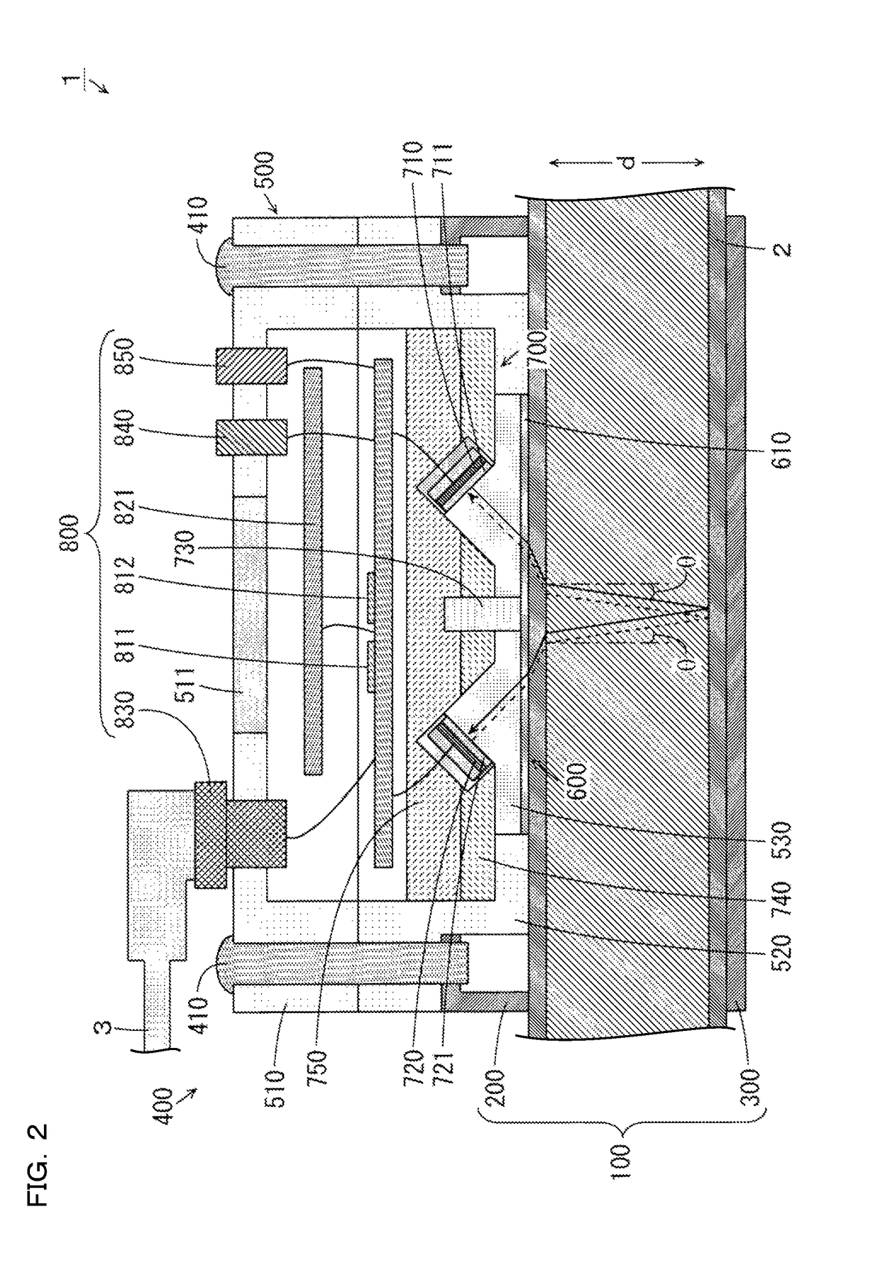
[0089]Hereinafter, an ultrasonic flow switch (hereinafter referred to as “flow switch” in short) according to one embodiment of the present invention is described with reference to drawings. FIG. 1 is a perspective view showing an external appearance of a flow switch according to one embodiment of the present invention. FIG. 2 is a schematic transverse cross-sectional view showing the internal configuration of a flow switch 1 shown in FIG. 1. As shown in FIG. 1, the flow switch 1 is formed of a clamp part 100 and a sensor part 400.

[0090]The clamp part 100 includes an upper clamp member 200 and a lower clamp member 300. The clamp part 100 is arranged such that a pipe 2 is sandwiched by the upper clamp member 200 and the lower clamp member 300. With such a configuration, the clamp part 100 is mounted on an outer peripheral surface of a pipe 2. In the example shown in FIGS. 1 and 2, an inner diameter of the pipe 2 is indicated ...


PUM


Abstract

Provided is an ultrasonic flow switch which can be stably mounted on pipe. A clamp part is mounted on an outer surface of the pipe. A casing part which integrally or independently holds the first and second ultrasonic wave elements is fixed to the clamp part by a sensor fixing screw. The clamp part is configured to restrict displacement of the casing part in an axial direction of the pipe and in a circumferential direction of the pipe and to allow displacement of the casing part in a radial direction of the pipe in a state where the casing part is not fixed.

Description

CROSS-REFERENCE TO RELATED APPLICATIONS[0001]The present application claims foreign priority based on Japanese Patent Application No. 2015-099219, filed May 14, 2015, the contents of which is incorporated herein by reference.BACKGROUND OF THE INVENTION[0002]1. Field of the Invention[0003]The present invention relates to an ultrasonic flow switch which is operable based on a flow rate of a fluid which flows in a pipe.[0004]2. Description of Related Art[0005]A flow meter is used for accurately measuring a value of a flow rate of a fluid which flows in a pipe. For example, JP-A-2001-356032 discloses an ultrasonic flow meter having a sensor. The sensor can measure a flow rate of a fluid which flows in a pipe using an ultrasonic wave. In the sensor, two sleigh-like blades which project downward are formed. A sheet-like silicone gel is arranged between two blades. The sensor is fixed to an outer peripheral surface of a pipe by being fastened by a fastening band such that bottom sides of t...

Claims


Application Information

Patent Timeline
Patent Type & Authority Patents(United States)
IPC IPC(8): G01F1/66G01F15/14G01F15/18
CPCG01F1/662G01F1/667G01F15/14G01F15/18
Inventor OTSU, SHINICHIROISHIKAWA, DAISHIRO
Owner KEYENCE
Learn More