Operating a display of a user equipment

a technology for user equipment and display, applied in the direction of acquiring/recognising eyes, program/content distribution protection, instruments, etc., can solve the problems of at least partly obscured objects, difficult to get sharp vision of objects, etc., and achieve low additional effort and stable over time

Active Publication Date: 2017-06-06
SONY CORP
View PDF17 Cites 4 Cited by
  • Summary
  • Abstract
  • Description
  • Claims
  • Application Information

AI Technical Summary

Benefits of technology

[0006]According to an aspect of the present invention, a method for operating a display of a user equipment is provided. The display of the user equipment is configured to display an object, for example an image or a video or a thumbnail of an image or a video, and a permission is assigned to the object. The permission defines an allowance for a person to view the object. For example, the permission may define a plurality of user identifiers related to single persons or to groups of persons. According to the method, a gaze position of a person looking at the display is determined. The gaze position defines a position on the display at which the person is currently looking. Furthermore, a distance between the gaze position and a position of the object is determined. Based on the permission which is assigned to the object, it is determined if the person is allowed to view the object. If the person is not allowed to view the object, the object is concealed depending on the determined distance between the gaze position and the position of the object. In other words, if the person is not allowed to view the object, the object may automatically be concealed when the person is looking at the position of the object or at a position near the object. Thus, privacy of an object like a photo or a video may be assured.
[0008]According to an embodiment, for concealing the object the object may be blurred. A degree of the blurring may be a monotonic function of the distance between the gaze position and the position of object. The degree of blurring increases when the distance becomes smaller. This gradual blurring of the object allows a limited area of the display surface to be used more efficiently while also giving a subtle indication that a gaze of a person who is not allowed to look at the object is coming closer to the object. The object may be completely blurred or only partly. Additionally or as an alternative, for concealing the object, the object may be removed from the display. Furthermore, as an alternative, the object may at least partly be obscured. Additionally, an output may be displayed on the display, for example partly or completely covering the object, indicating that a gaze position of a person which has no permission to view the object is approaching the object.
[0010]According to an embodiment, for determining if the person is allowed to view the object, an image of an iris of the person is captured and an identifying information for the person is determined based on the image of the iris. Based on the permission assigned to the object and the identifying information for the person is determined, if the person is allowed to view the object. Identification using the iris is a very secure method for identifying a person. The iris pattern is stable over time and is unique for every person including twins and even unique for each eye of the same person. As for determining the gaze position, the eye of the person has to be captured anyway, iris identification may be performed with low additional effort.
[0012]According to a further embodiment, for capturing the image of the iris of the person, the eye of the person is illuminated subsequently from a plurality of different directions. While the eye of the person is illuminated from the plurality of different directions, a plurality of images of the iris of the person is subsequently captured. For example, the eye of the person may be illuminated subsequently from nine different directions, for example from nine differently arranged light sources, and for every illumination direction a corresponding image of the iris is captured. The image of the iris is determined by combining the captured plurality of images. When using for example infrared light sources, for example infrared light emitting diodes (LED), reflections may be generated in the cornea. Such reflections may cover or obscure details in the iris and thus make the identification of the person via the above-described iris identification less reliable. By using a number of differently located infrared LEDs and switching between them it is possible to combine several images using for example feature extraction algorithms, to create an image without or with less of the corneal reflections being present. The plurality of different light sources can be used both for determining the gaze position and for iris identification.

Problems solved by technology

With the current user interfaces this becomes difficult in contrast to traditional methods like searching photos in a photo box or a photo album where it is easier to skip parts or to occlude parts that should not be shared.
In case the person who is not allowed to view the object is looking at the object only peripherally, the object need not to be concealed, as in this case the person is not able to get a sharp vision of the object.
Furthermore, as an alternative, the object may at least partly be obscured.
Such reflections may cover or obscure details in the iris and thus make the identification of the person via the above-described iris identification less reliable.

Method used


Image

  • Operating a display of a user equipment
  • Operating a display of a user equipment
  • Operating a display of a user equipment

Examples


Embodiment Construction

[0024]In the following, exemplary embodiments of the present invention will be described in more detail. It is to be understood that the features of the various exemplary embodiments described herein may be combined with each other unless specifically noted other wise.

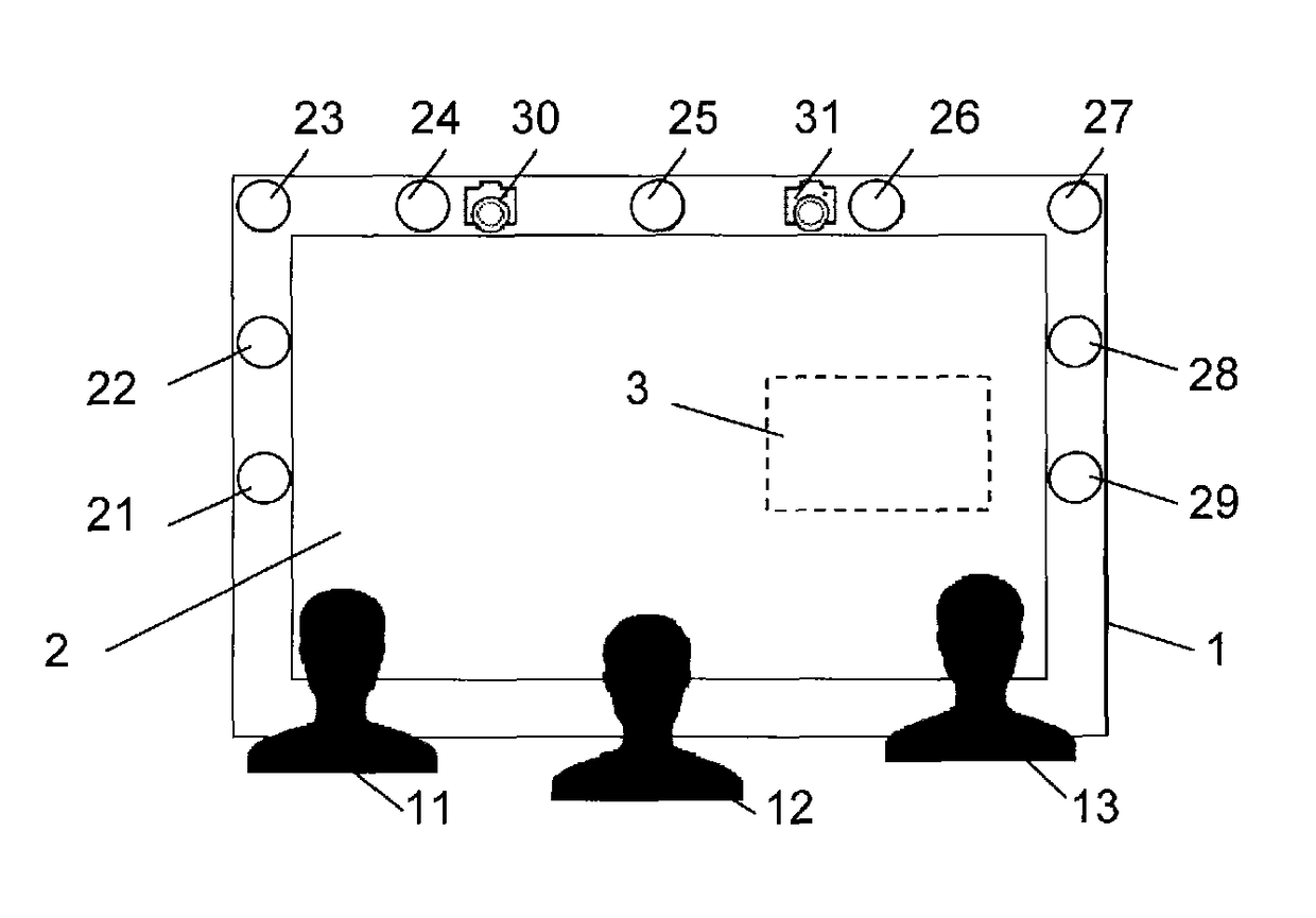
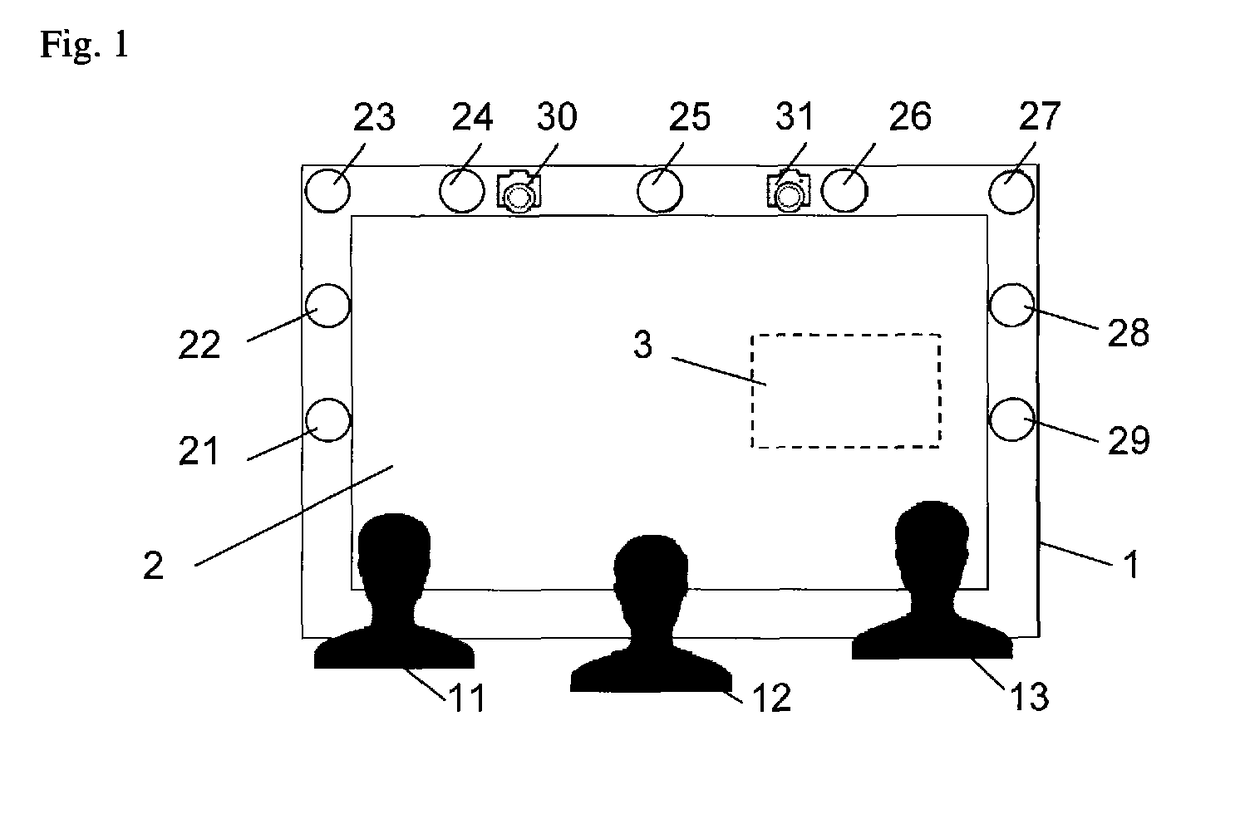
[0025]FIG. 1 shows schematically a user equipment 1. The user equipment 1 may comprise for example a mobile telephone, for example a so-called smartphone, a tablet PC, a computer monitor or a flatscreen of a home entertainment system or a flatscreen of a collaborating surface arranged for example at a wall or in a desk in an office. The user equipment 1 comprises a display 2, for example a liquid crystal display, on which information for persons 11-13 looking at the user equipment 1 may be presented. The information presented on the display 2 may comprise for example photos, images, drawings, charts, diagrams, videos or text documents or a combination thereof. The user equipment 1 comprises furthermore a plurality of i...


PUM


Abstract

Operating a display of a user equipment. The present invention relates to a method for operating a display (2) of a user equipment (1). The display (2) is configured to display an object (50). A permission is assigned to the object (50), which defines an allowance for a person (11-13) to view the object (50). According to the method, a gaze position (63) of a person (12) looking at the display (2) is determined, which defines a position on the display (2) at which the person (12) is looking. A distance between the gaze position (63) and a position of the object (50) is determined and furthermore, it is determined, if the person (12) is allowed to view the object based on the permission assigned to the object (50). If the person (12) is not allowed to view the object (50), the object (50) is concealed depending on the determined distance between the gaze position (63) and the position of the object (50).

Description

TECHNICAL FIELD[0001]The present invention relates to a method for operating a display of a user equipment, especially to a method for avoiding that a user who has no permission to look at a certain object, which is to be displayed on the display, can see the object. The present invention relates furthermore to a user equipment implementing the method.BACKGROUND ART[0002]More and more of information of our daily life is stored digitally and becomes easier to share with other people. For example, images and videos may be stored on a user equipment, for example a tablet PC, a desktop PC, a mobile telephone, especially a smartphone or a media center in a living room, and may be available to be viewed on a display of the tablet PC or desktop PC or on a TV flatscreen. In this case, several people are enabled to watch the information stored. The same may occur in case of a flatscreen collaboration surface in an office environment. There may be some information to share, but other informat...

Claims


Application Information

Patent Timeline
Patent Type & Authority Patents(United States)
IPC IPC(8): G06F21/62G06K9/00G06F21/32G06F21/60G06F21/84G06F3/0481G06F3/01H04N13/04G06F21/10G06F21/50G06F21/64
CPCG06F21/84G06F3/013G06F3/0481G06F21/10G06F21/32G06F21/60G06F21/6245G06K9/00597G06K9/00604H04N13/0484G06F21/50G06F21/645G06F2221/032H04N13/383G06V40/19G06V40/18
Inventor THORN, OLAARONSSON, PAR-ANDERS
Owner SONY CORP
Why Eureka
Try Eureka