Method of making stretchable interconnect using magnet wires

a technology of magnet wires and interconnections, which is applied in the direction of flexible printed circuits, circuit bendability/stretchability, printed circuit aspects, etc., can solve the problem that metal wires themselves are not stretchabl

Inactive Publication Date: 2017-06-06
FLEXTRONICS AP LLC
View PDF123 Cites 29 Cited by
  • Summary
  • Abstract
  • Description
  • Claims
  • Application Information

AI Technical Summary

Benefits of technology

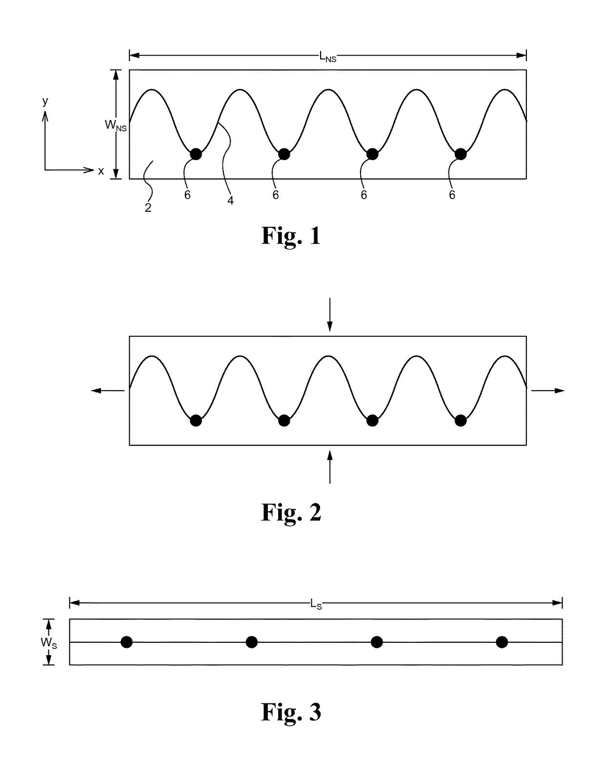
[0006]In some embodiments, the second elastic substrate has a relaxed, non-stretched state, and is configured to be stretched along at least the first direction when the stretching force is applied along the first direction, and to return to the non-stretched state when the stretching force is removed. In some embodiments, the first elastic substrate and the second elastic substrate are configured to be stretched along a second direction different than the first direction and the metal wire forms the tortuous path relative to the first direction and the second direction. In some embodiments, the first elastic substra...

Problems solved by technology

Although metal wires are bendable, such as in an e...

Method used


Image

  • Method of making stretchable interconnect using magnet wires
  • Method of making stretchable interconnect using magnet wires
  • Method of making stretchable interconnect using magnet wires

Examples


Embodiment Construction

[0019]Embodiments of the present application are directed to a stretchable metal wire assembly. Those of ordinary skill in the art will realize that the following detailed description of the stretchable metal wire assembly is illustrative only and is not intended to be in any way limiting. Other embodiments of the stretchable metal wire assembly will readily suggest themselves to such skilled persons having the benefit of this disclosure.

[0020]Reference will now be made in detail to implementations of the stretchable metal wire assembly as illustrated in the accompanying drawings. The same reference indicators will be used throughout the drawings and the following detailed description to refer to the same or like parts. In the interest of clarity, not all of the routine features of the implementations described herein are shown and described. It will, of course, be appreciated that in the development of any such actual implementation, numerous implementation-specific decisions must ...


PUM

PropertyMeasurementUnit
Adhesion strengthaaaaaaaaaa
Elasticityaaaaaaaaaa
Stretching forceaaaaaaaaaa

Abstract

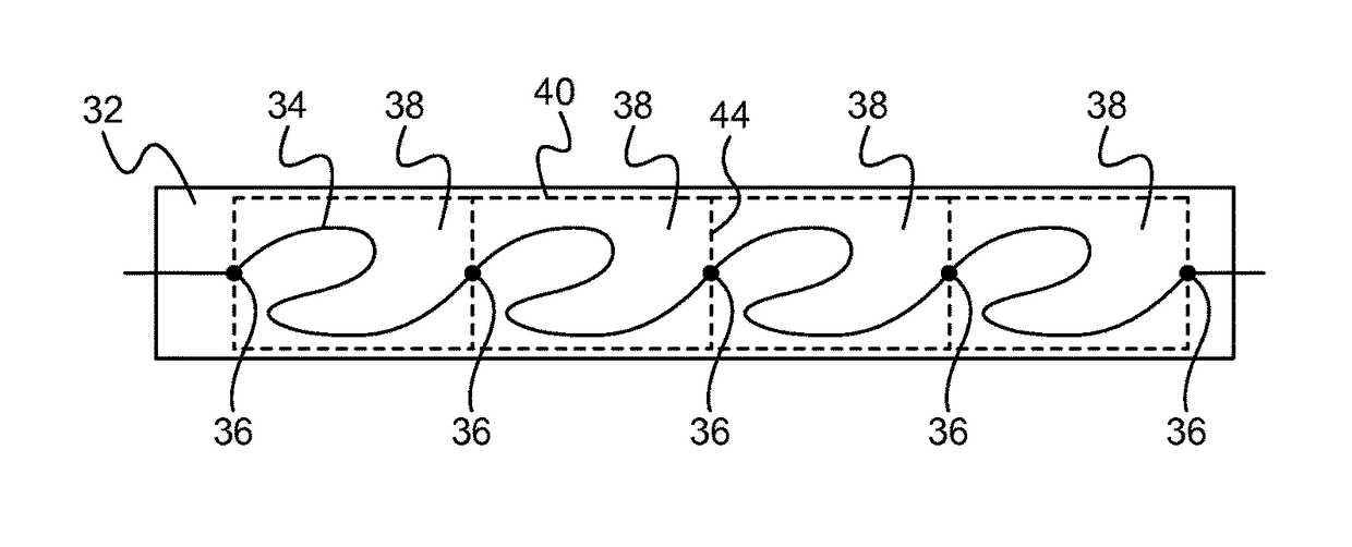
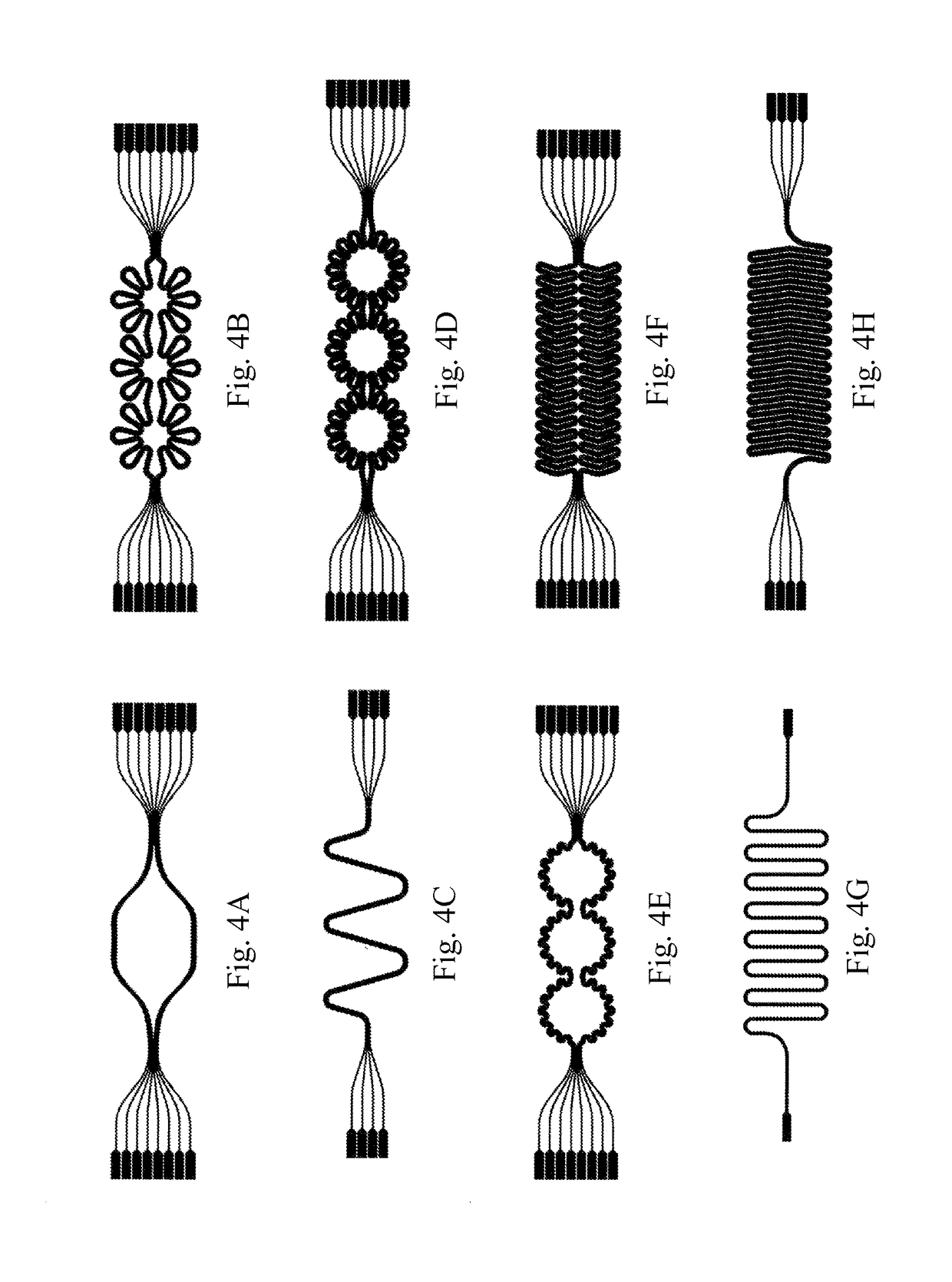
A stretchable wire assembly includes a metal wire coupled between two elastic substrates. The two elastic substrates are selectively coupled together, and the metal wire is attached to one or both elastic substrates at select locations. The form of the metal wire is such that when the elastic substrates are in a relaxed, or non-stretched, state the metal wire forms a tortuous path, such as a waveform, along the coupled elastic substrates. The tortuous path of the metal wire provides slack such that as the elastic substrates are stretched the slack is taken up. Once released, the elastic substrates move from the stretched position to the relaxed, non-stretched position, and slack is reintroduced into the metal wire in the form of the original tortuous path.

Description

RELATED APPLICATIONS[0001]This patent application is a continuation-in-part of U.S. patent application Ser. No. 14 / 145,815, filed Dec. 31, 2013, and entitled “Stretchable Metal Wire Assembly”. U.S. patent application Ser. No. 14 / 145,815 claims priority under 35 U.S.C. 119(e) of the U.S. Provisional Application Ser. No. 61 / 870,627, filed Aug. 27, 2013, and entitled “Interconnect Methods” and U.S. Provisional Application Ser. No. 61 / 870,646, filed Aug. 27, 2013, and entitled “Stretchable Metals”. This patent application also claims priority under 35 U.S.C. 119(e) of the U.S. Provisional Application Ser. No. 61 / 913,830, filed Dec. 9, 2013, and entitled “Metal Fabric Stitching and Stretchable Batteries”. This patent application incorporates U.S. patent application Ser. No. 14 / 145,815, U.S. Provisional Application Ser. No. 61 / 870,627, U.S. Provisional Application Ser. No. 61 / 870,646 and U.S. Provisional Application Ser. No. 61 / 913,830 in their entireties by reference.FIELD OF THE INVENTI...

Claims


Application Information

Patent Timeline
IPC IPC(8): H05K1/02H05K1/09H05K1/11
CPCH05K1/0283H05K1/09H05K1/118H05K1/028H05K1/11H05K2201/05H05K2201/032H05K2201/0162H05K2201/0137H05K1/145H05K2201/10287
Inventor LIU, WEIFENGFENG, ZHENMOHAMMED, ANWAR
Owner FLEXTRONICS AP LLC
Why Eureka
Try Eureka