Wireless actuator circuit for wireless actuation of micro electromechanical system switch for magnetic resonance imaging

a micro electromechanical system and actuator circuit technology, applied in the field of magnetic resonance imaging, can solve the problems of long patient set up time and patient discomfor

Inactive Publication Date: 2017-06-13
GENERAL ELECTRIC CO
View PDF12 Cites 14 Cited by
  • Summary
  • Abstract
  • Description
  • Claims
  • Application Information

AI Technical Summary

Problems solved by technology

The increasing number of cables leads to longer patient set up time as well as patient discomfort during imaging as these MRI coils are placed around the patient.

Method used


Image

  • Wireless actuator circuit for wireless actuation of micro electromechanical system switch for magnetic resonance imaging
  • Wireless actuator circuit for wireless actuation of micro electromechanical system switch for magnetic resonance imaging
  • Wireless actuator circuit for wireless actuation of micro electromechanical system switch for magnetic resonance imaging

Examples


Embodiment Construction

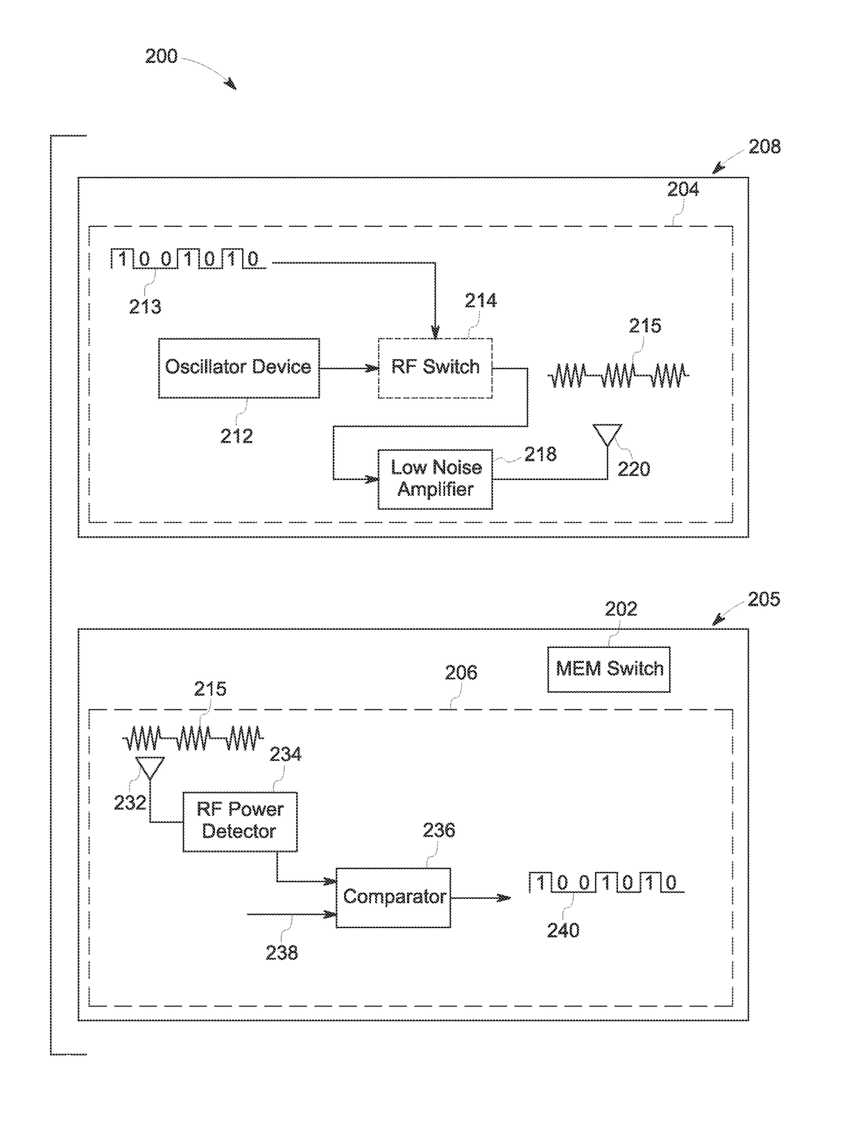
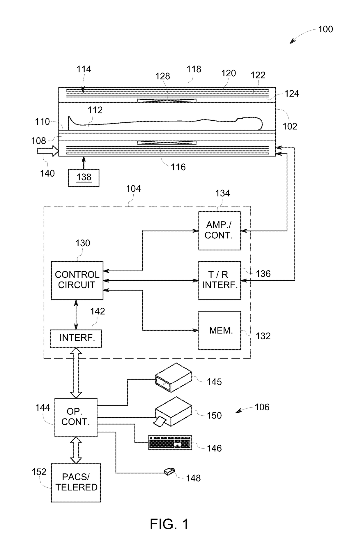
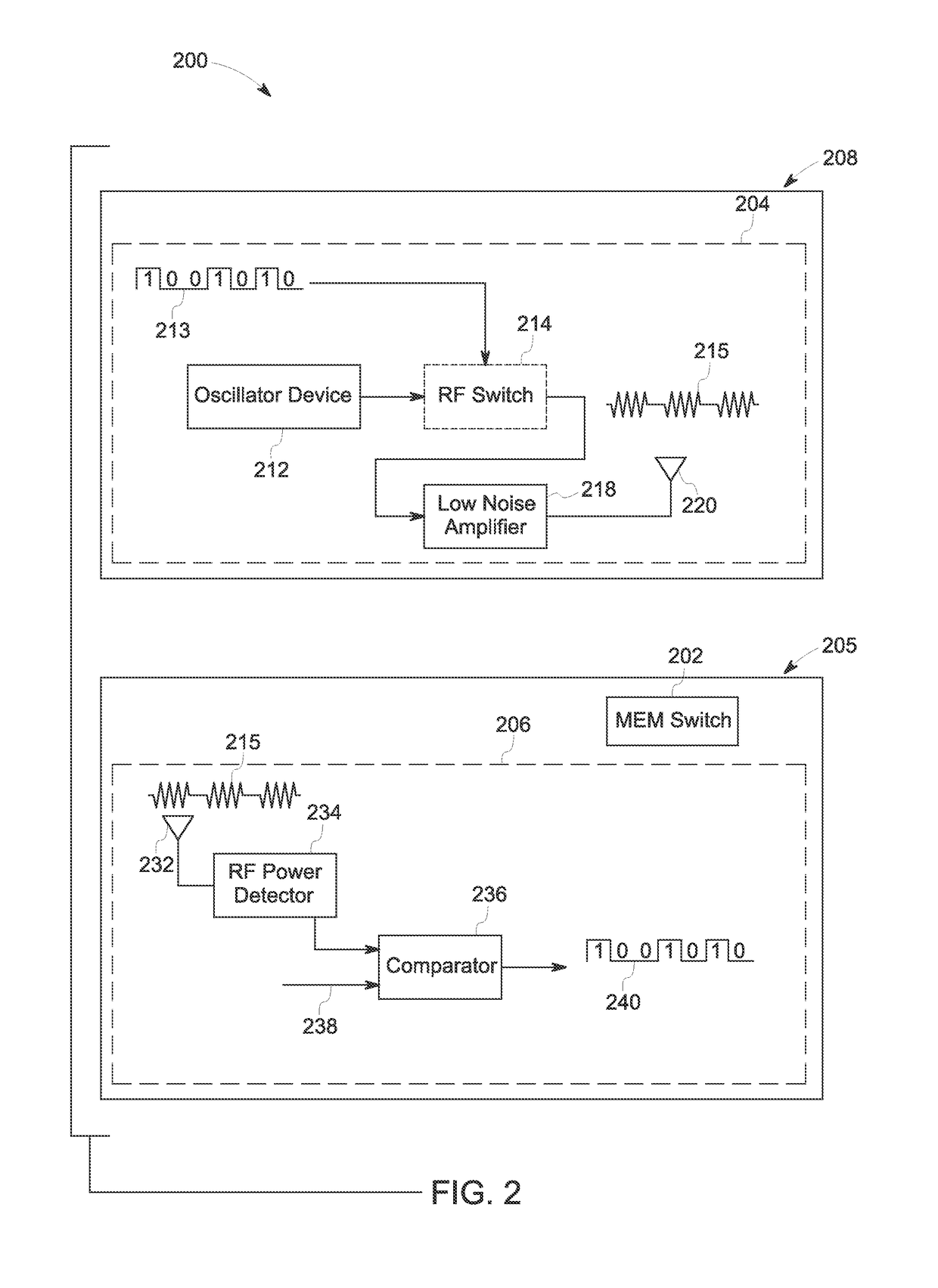
[0016]Embodiments of the present specification relate to systems and methods for wireless actuation of a micro electromechanical system (MEMS) switch for magnetic resonance imaging (MRI). Typically, a MRI system employs a switch to enable and / or disable receiver coils of the MRI system during image acquisition. By way of example, the receiver coils are disabled during a transmitting mode of the MRI system, and enabled during a receiving mode of the MRI system. Generally, the switch is configured to be actuated using wired connections. Some of the existing MRI systems employ a MEMS switch instead of a pin diode to enhance switching speed of the switch configured to enable and / or disable the receiver coils in the MRI system. Further, sometimes, a low power MEMS switch is used to facilitate high speed switching of the receiver coils. However, with a wired implementation of the MEMS switch, switching latencies of the MEMS switch are relatively high. Further, these switching latencies at...


PUM


Abstract

A wireless actuator circuit configured to actuate a micro electromechanical system (MEMS) switch is provided. The wireless actuator circuit includes a transmitter portion and a receiver portion operatively coupled to the transmitter portion. The transmitter portion includes an oscillator device configured to generate a signal at a determined frequency and a first antenna operatively coupled to the oscillator device to receive a modulated signal. Further, the receiver portion includes a second antenna configured to receive the modulated signal from the transmitter portion, a radio frequency power detector configured to detect the modulated signal and a comparator configured to produce a control signal in response to the modulated signal detected by the radio frequency power detector to toggle the MEMS switch.

Description

BACKGROUND[0001]Embodiments of the present specification relate to magnetic resonance imaging (MRI), and more particularly to wireless actuation of MRI coils.[0002]As will be appreciated, when a substance such as human tissue is subjected to a uniform magnetic field (polarizing field B0), individual magnetic moments of spins in tissues attempt to align with the applied polarizing field. However, the individual magnetic moments of the spins precess about this polarizing field in random order at their characteristic Larmor frequency. If the substance or tissue is subjected to a magnetic field (excitation field B1) which is in the x-y plane and the magnetic field is near the Larmor frequency, the net aligned moment, or “longitudinal magnetization”, MZ, may be rotated, or “tipped,” into the x-y plane to produce a net transverse magnetic moment, Mt. Further, a signal is emitted by excited spins after the excitation field, B1, is terminated. This emitted signal may be acquired and process...

Claims


Application Information

Patent Timeline
Patent Type & Authority Patents(United States)
IPC IPC(8): G01R33/36H01H9/54
CPCG01R33/3692G01R33/3657H01H9/54
Inventor BULUMULLA, SELAKA BANDARAIANNOTTI, JOSEPH ALFREDWIK, STEVEN WILLIAM
Owner GENERAL ELECTRIC CO
Why Eureka
Try Eureka