
Method of altering the refractive properties of an eye

a technology of refractive properties and eye, applied in the field of eye surgery, can solve the problems of ametropia, inability of the lens and cornea to accurately focus the far point, and astigmatic eye inability to sharply focus images on the retina, so as to facilitate cross-linking of the portion, reduce postoperative pain, and alter the refractive properties of the eye

Inactive Publication Date: 2017-06-20
PEYMAN GHOLAM A
View PDF23 Cites 4 Cited by
  • Summary
  • Abstract
  • Description
  • Claims
  • Application Information

AI Technical Summary

Benefits of technology

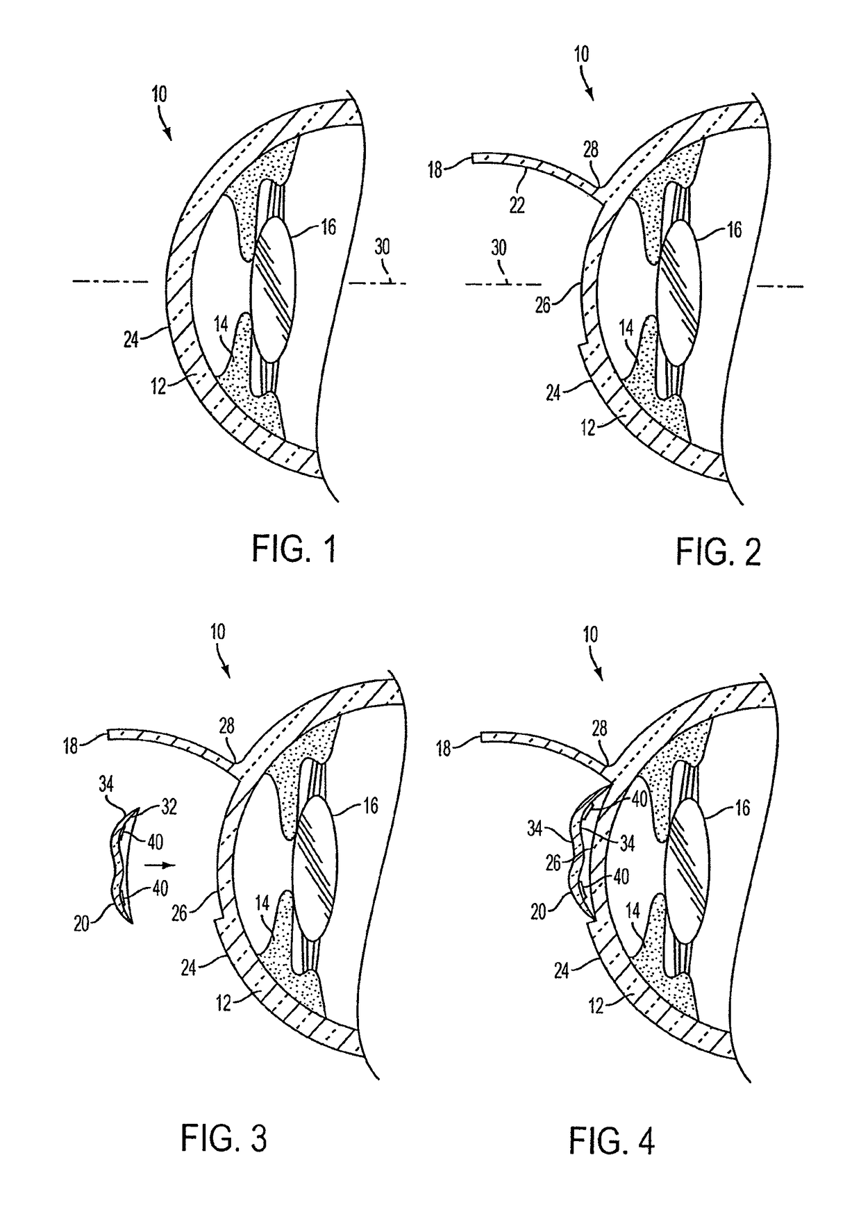
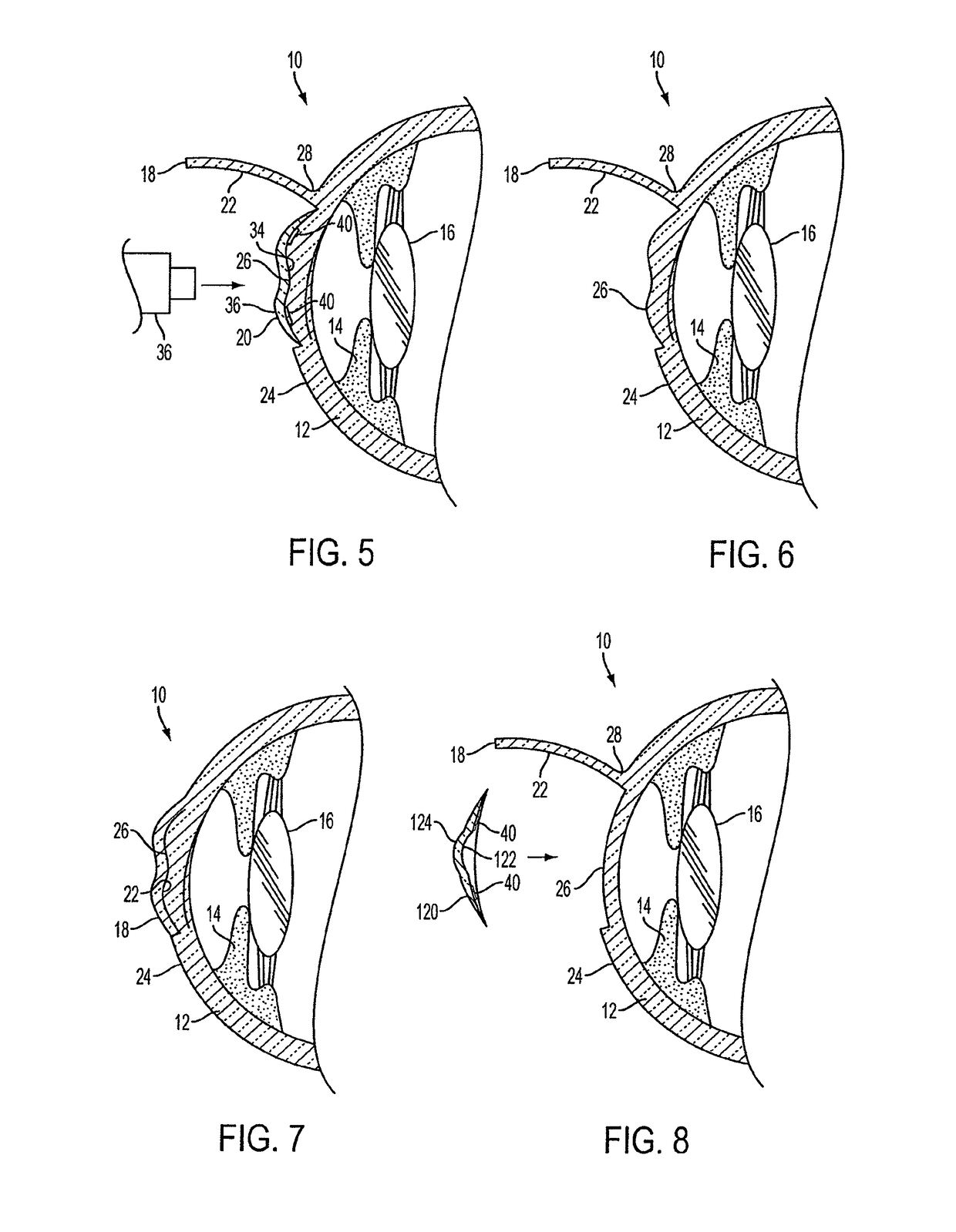
[0022]In accordance with one or more embodiments of the present invention, there is provided a method of altering the refractive properties of the eye. The method comprising the steps of: (i) forming a flap in a cornea of an eye so as to expose a portion of the cornea underlying the flap; (ii) pivoting the flap so as to expose the portion of the cornea underlying the flap; (iii) ablating the portion of the cornea underlying the flap so as to change the refractive properties of the eye; (iv) after the portion of the cornea underlying the flap has been ablated, applying a photosensitizer to the ablated portion of the cornea underlying the flap, the photosensitizer facilitating cross-linking of the ablated portion of the cornea; (v) replacing the flap over the ablated portion of the cornea; and (vi) irradiating the cornea so as to activate cross-linkers in the ablated portion of the cornea and thereby stiffen the cornea and prevent corneal ectasia of the cornea.
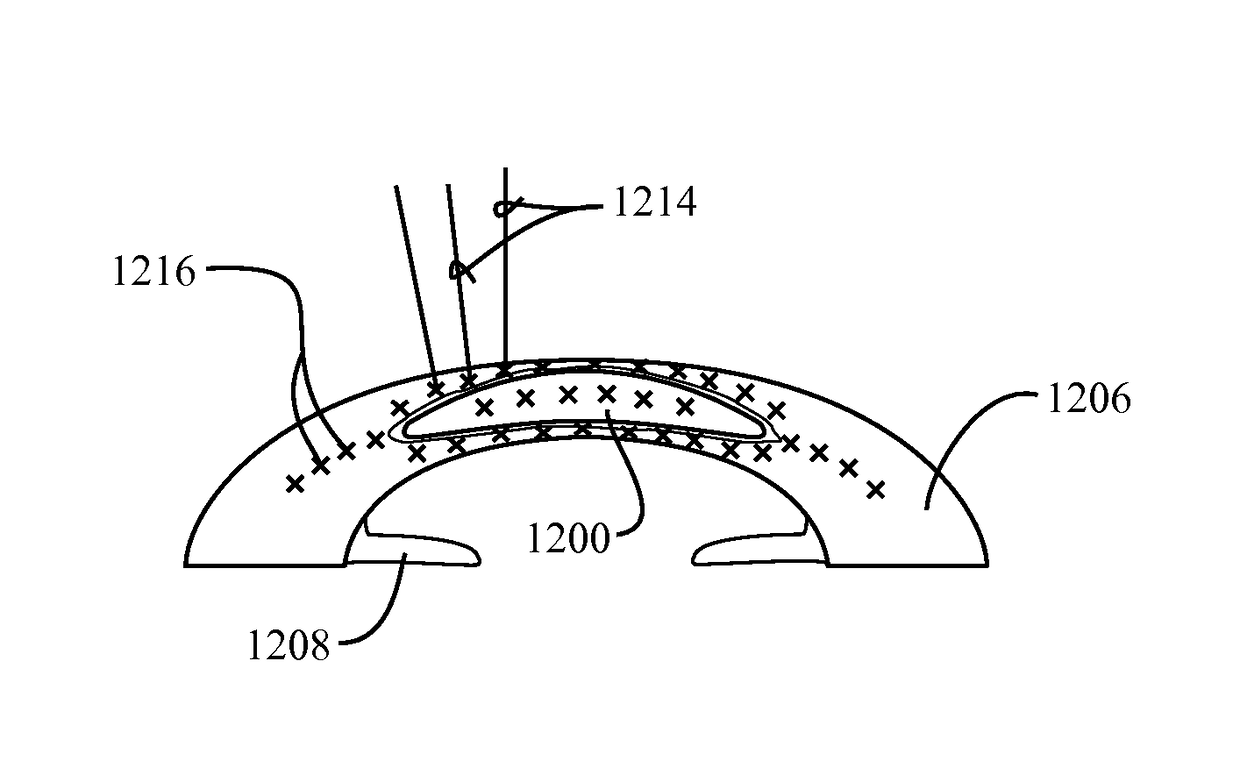
[0030]In accordance with one or more other embodiments of the present invention, there is provided a method of altering the refractive properties of the eye. The method comprising the steps of: (i) forming a pocket in a cornea of an eye so as to gain access to tissue bounding the pocket; (ii) after the pocket in the cornea has been formed, applying a photo sensitizer inside the pocket so that the photosensitizer permeates at least a portion of the tissue bounding the pocket, the photosensitizer facilitating cross-linking of the tissue bounding the pocket; (iii) irradiating the cornea so as to activate cross-linkers in the portion of the tissue bounding the pocket and thereby stiffen the cornea and prevent corneal ectasia of the cornea; and (iv) after the cornea has been stiffened by the activation of the cross-linkers, ablating a front surface of the cornea so as to change the refractive properties of the eye, or inserting a lens implant into the pocket so as to change the refractive properties of the eye.
[0039]In still a further embodiment, the step of forming the pocket in the cornea of the eye includes cutting the pocket using a femtosecond laser or a mechanical keratome, and wherein the forming of the pocket with the femtosecond laser or the mechanical keratome reduces the postoperative pain sensation that is felt by a patient when the front surface of the cornea is ablated.
[0040]In accordance with yet one or more other embodiments of the present invention, there is provided a method of altering the refractive properties of the eye. The method comprising the steps of: (i) soaking a lens implant in a cross-linking solution that includes a photosensitizer, the lens implant having a predetermined shape for changing the refractive properties of an eye; (ii) forming a pocket in a cornea of the eye; (iii) after the pocket in the cornea has been formed, inserting the lens implant with the photosensitizer thereon inside the pocket so that the photosensitizer permeates at least a portion of the tissue bounding the pocket, the photosensitizer facilitating cross-linking of the portion of the tissue bounding the pocket; and (iv) irradiating the cornea so as to activate cross-linkers in the portion of the tissue bounding the pocket and thereby stiffen the cornea and prevent corneal ectasia of the cornea.

Problems solved by technology

However, an eye can have a disorder known as ametropia, which is the inability of the lens and cornea to focus the far point correctly on the retina.
Therefore, an astigmatic eye is incapable of sharply focusing images on the retina.
Although these optical methods can be used to correct vision in eyes suffering from low myopia, or in eyes suffering from hypermetropic, hyperopic or astigmatic conditions which are not very severe, these methods are ineffective in correcting vision in eyes suffering from severe forms of ametropia.
Altering the shape of the cut portion of the cornea changes the refractive power of this cut portion, which thus affects the location at which light entering the cut portion of the cornea is focused.
However, the technique is impractical because it employs very complicated and time consuming freezing, cutting and thawing processes.
However, the keratophakia technique is relatively impractical, complicated, and expensive because it requires manufacturing or cutting a special lens prior to its insertion into the cornea.
Hence, a surgeon is required to either maintain an assortment of many differently shaped lenses, or alternatively, must have access to expensive equipment, such as a cyrolathe, which can be used to cut the lens prior to insertion into the cornea.
However, because only a certain amount of cornea can be ablated without the remaining cornea becoming unstable or experiencing outwardbulging (ectasia), this technique is not especially effective in correcting very high myopia.
Hence, this method typically cannot be effectively used to correct high myopia of greater than 15 diopters because, in order to reshape the cornea to the degree necessary to alter its refractive power to sufficiently correct the focusing of the eye, too much of the cornea would need to be ablated.
Furthermore, since the cornea can generally only be shrunk in response to thermal coagulation, this method is exclusively used for presbyopic and hyperopic correction of refractive errors.

Method used


Image

  • Method of altering the refractive properties of an eye
  • Method of altering the refractive properties of an eye
  • Method of altering the refractive properties of an eye

Examples


Embodiment Construction

[0021]Accordingly, the present invention is directed to a method of altering the refractive properties of the eye that substantially obviates one or more problems resulting from the limitations and deficiencies of the related art.

[0022]In accordance with one or more embodiments of the present invention, there is provided a method of altering the refractive properties of the eye. The method comprising the steps of: (i) forming a flap in a cornea of an eye so as to expose a portion of the cornea underlying the flap; (ii) pivoting the flap so as to expose the portion of the cornea underlying the flap; (iii) ablating the portion of the cornea underlying the flap so as to change the refractive properties of the eye; (iv) after the portion of the cornea underlying the flap has been ablated, applying a photosensitizer to the ablated portion of the cornea underlying the flap, the photosensitizer facilitating cross-linking of the ablated portion of the cornea; (v) replacing the flap over the...


PUM


Abstract

The present invention relates to a method of altering the refractive properties of the eye, the method including applying a substance to a cornea of an eye, the substance configured to facilitate cross linking of the cornea, irradiating the cornea so as to activate cross linkers in the cornea, and altering the cornea so as to change the refractive properties of the eye.

Description

CROSS-REFERENCE TO RELATED APPLICATIONS[0001]This application is a continuation-in-part of U.S. patent application Ser. No. 12 / 770,011, filed Apr. 29, 2010, entitled “Method for Laser Correction of Refractive Errors of an Eye with a Thin Cornea”, now U.S. Pat. No. 9,155,652, and which is a continuation-in-part of U.S. patent application Ser. No. 12 / 608,249, filed Oct. 29, 2009, entitled “Method for Prevention of Rejection and Sever Encapsulation of a Supportive or Functioning Implant”, now pending and which is a continuation-in-part of U.S. patent application Ser. No. 11 / 676,793 filed Feb. 20, 2007, entitled “Method and System for Altering the Refractive Properties of the Eye”, now abandoned and which is a continuation-in-part of U.S. patent application Ser. No. 11 / 446,065, filed Jun. 1, 2006. entitled “Device and Method for Reshaping the Cornea”, now abandoned and which is a continuation-in-part of application of U.S. patent application Ser. No. 11 / 070,659, filed Mar. 2, 2005, enti...

Claims


Application Information

Patent Timeline
Patent Type & Authority Patents(United States)
IPC IPC(8): A61F9/007A61F9/008A61F9/013A61F7/00A61F9/009
CPCA61F9/0079A61F9/007A61F9/0081A61F9/00804A61F9/00812A61F9/00814A61F9/00821A61F7/007A61F9/008A61F9/009A61F9/00827A61F9/0133A61F2007/0004A61F2007/0054A61F2009/0088A61F2009/00853A61F2009/00872A61F2009/00893A61F2009/00897
Inventor PEYMAN, GHOLAM A.
Owner PEYMAN GHOLAM A
Learn More