
Seamless illuminated panel

a technology of illuminated panels and modules, applied in fixed installations, lighting and heating apparatuses, instruments, etc., can solve the problems of high cost, high weight, high cost, and high cost of units, and achieve the effect of reasonable cost and easy assembly

Inactive Publication Date: 2017-06-20
LELLAN
View PDF11 Cites 3 Cited by
  • Summary
  • Abstract
  • Description
  • Claims
  • Application Information

AI Technical Summary

Benefits of technology

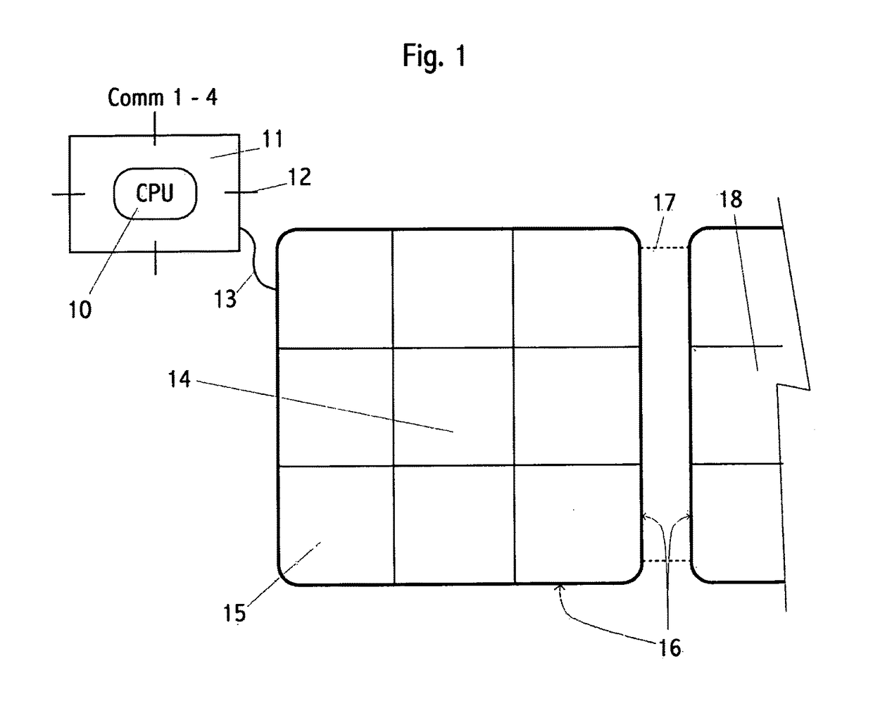
[0011]Embodiments of this invention include tiles and tiled panels comprised of adjacent tiles to form a smooth, flat panel capable of producing dynamic images in color while providing a uniform diffuse light surface, for a reasonable cost, using easily assembled and re-usable tiles.
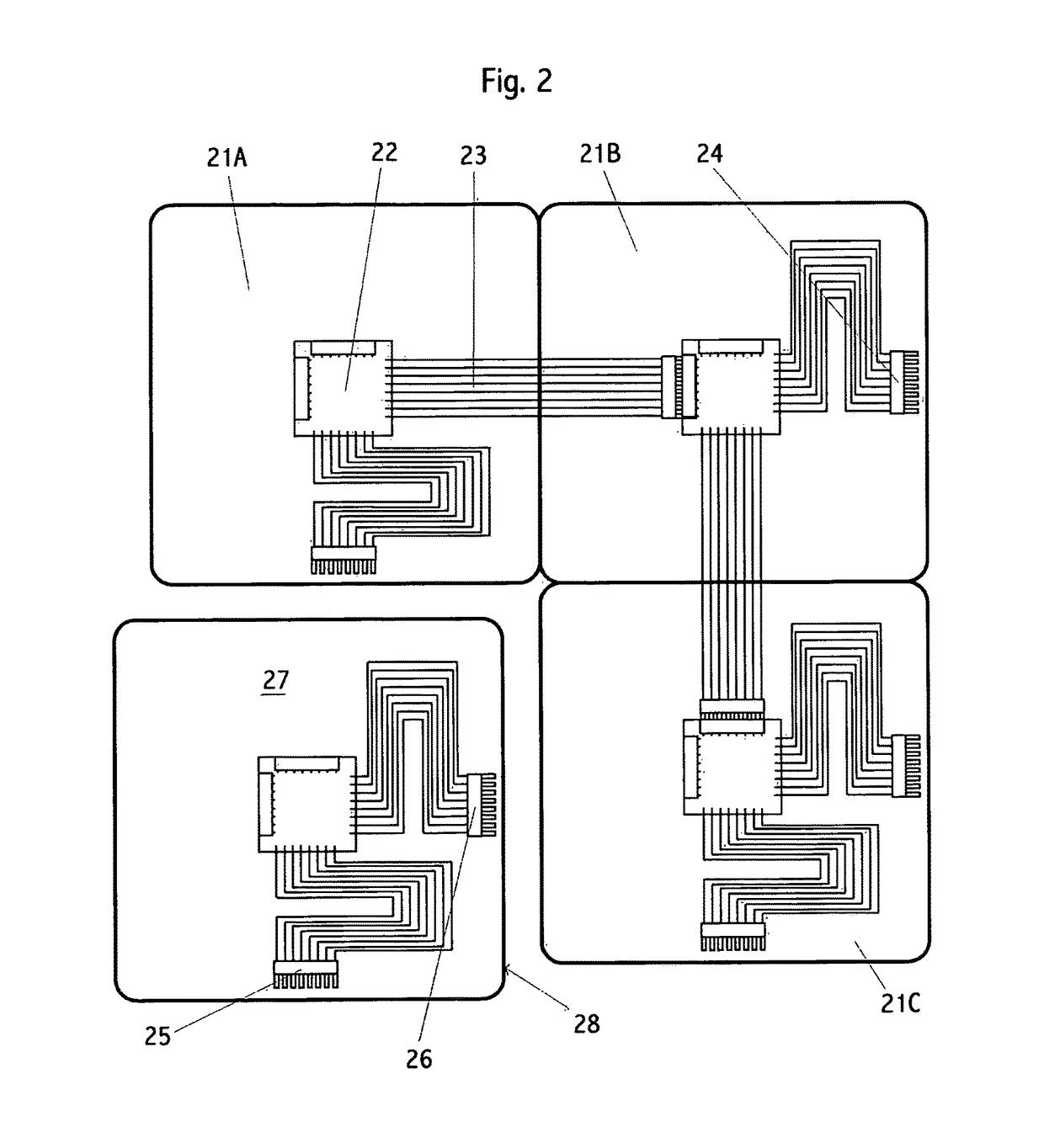
[0018]A completed modular panel, which is typically constructed in the field, comprises an array of adjacent base plates mounted on a structural support surface and interconnected; a corresponding illumination plate affixed to and electrically connected to each base plate; and a power source and control source attached to one base plate. Each base plate is effectively the same and each illumination plate is effectively the same, permitting simplified field installation of a wide range of panel sizes, shapes, and purposes from a simple inventory of (i) base plates; (ii) illumination plates; (iii) uniform interconnection cables, (iv) uniform interconnection fasteners; (v) one or more power sources and controllers (which may be combined into a single electronic module). Ideally, both the individual base plates and illumination plates may be installed in any of four rotational positions.
[0025]Base plates should be re-usable, lightweight, low-cost, with a low mechanical depth, such as no more than one quarter the width of the tile, and preferably, no more than one-eighth the width of a tile. Base plates should preferably be mountable and removable from a structural support surface, such as a wall, floor, ceiling, partition or shelf, with a single tool, such as a screwdriver. Base plates should each be positionable in at least two, and preferably four, rotations without negative impact on the configuration or performance of a completed panel.

Problems solved by technology

Such a format is ideal for large video projection requirements, however, such units are very expensive, large, deep, power-hungry, and complex.
The weaknesses of the first format are high cost, high weight, a need for continuous video data stream, and high complexity.
The weaknesses of the second format are that it does not provide a large area display for a low cost per unit area, and that it does not provide a uniform, diffuse light capability.
Such devices are not suitable for implementing as tiles, due to the lack of built-in processing, image and color adjustment, rectangular shape, mechanical interconnections and flat light emitting surface.
Field assembly of panels requires only a small number of unique components, and minimal training.
Prior art does not provide these necessary attributes.
For example, U.S. Pat. No. 8,360,604 B2 does not provide ease of installation, minimal depth, uniform light, seamless image presentation, electrically inter-connectability, mechanical inter-connectability or self-configuration as a panel.
As another example, US patent publication US 2013 / 0181884 is a bulky, expensive system that does not provide ease of installation, light-weight, minimal depth, or high-efficiency.
Most prior art arrays of light emitting elements are in the form of fixed size manufactured panels and do not comprise re-usable, field installable modular, inter-connectable tiles.
Prior art illuminating panels provided either (1) sufficient light output and efficiency to be appropriate for area and task lighting, but failed to provide dynamic display of images; or (2) dynamic display of images but had insufficient light output or efficiency to be generally appropriate for area or task lighting.
Prior art for mood, architectural or ambient lighting lacked the ability to provide dynamic display of images.

Method used


Image

  • Seamless illuminated panel
  • Seamless illuminated panel
  • Seamless illuminated panel

Examples


embodiments

[0240]Various embodiments include:[0241]101. A tile for the purpose of providing illumination comprising:[0242]a plurality of illumination devices configured to provide colored light of different hues and brightnesses;[0243]a processor operatively connected to the illumination devices;[0244]a one or more communication interfaces operatively connected to the processor configured to connect to a plurality of similar tiles;[0245]wherein each tile edge is configured to optionally mate to a tile edge of an adjacent tile;[0246]wherein the processor is configured to receive over one or more of its communication interfaces hue and brightness commands.[0247]102. The tile of embodiment 101 wherein:[0248]the tile is rectangular.[0249]103. The tile of embodiment 101 wherein:[0250]the number of communication interfaces is three or more.[0251]104. The tile of embodiment 101 wherein:[0252]the processor controls the brightness and hue of each illumination device separately.[0253]105. The tile of em...


PUM


Abstract

A device and method of providing a versatile illuminated panel for walls, product displays, and other surfaces is described. Panels are constructed from a variable number of rectangular illuminated tiles, where the tiles mate edge-to-edge so as to create a nearly seamless visual panel effect. Illumination within each tile is uniform to also create a nearly seamless visual panel effect. End-users may create panels of varying sizes and shapes by using different quantities of a standard tile. The software within the invention automatically determines the number and arrangement of tiles within each assembled panel. Each tile comprises a plurality of illuminators, an optical means to distribute light from the illuminators uniformly across the tile, and at least one communication interface. In one embodiment the tiles are linked into a communications tree-structure; and the location of each tile within the tree constitutes its logical address.

Description

CROSS-REFERENCE TO RELATED APPLICATIONS[0001]This application claims the benefit of U.S. Provisional Application 61 / 721,454 filed 1 Nov. 2012 and is incorporated herein in its entirety.TECHNICAL FIELD[0002]The technical field of this invention is illuminated tiled modular display panels. In particular, field-installable modular illuminated panels comprising tiles that display images via a programmable array of pixels.BACKGROUND ART[0003]Background art includes both modular video display panels, and electronic imaging panels comprising an array of picture elements (pixels). For example, patent and patent application publications including: US20130181884, US20060044215, CN202841795, US2005212717, and WO2011159039.[0004]Prior art includes tiled display panels for the purpose of large area illuminated dynamic (electronic) image displays. What is in common with the instant invention is the use of interconnected tiles wherein the tiles form a larger panel. Such prior art comprises two for...

Claims


Application Information

Patent Timeline
Patent Type & Authority Patents(United States)
IPC IPC(8): G06F3/14H05B33/08H05B37/02F21V11/00F21V17/10F21S2/00F21S8/00G06F9/44F21Y105/00H05B44/00
CPCG06F3/1446F21S2/00F21S8/03F21V11/00F21V17/105H05B33/0857H05B37/0254F21Y2105/00G06F9/4413G09G2360/04F21V33/006H05B47/18H05B45/28
Inventor EKKAIA, DEANHALASZ, FRANKWIMMER, RICHARD ALFONS
Owner LELLAN
Learn More