
LED lightbulb minimizing LEDs for uniform light distribution

a technology of led lightbulb and light bulb body, which is applied in the field of lighting, can solve the problems of inefficient power consumption of conventional incandescent lightbulb and design that is less pleasing to the eye, and achieve the effects of minimizing the number of led elements, long lasting, and similar size and/or shap

Active Publication Date: 2017-06-27
PINATO ROBERT M
View PDF40 Cites 1 Cited by
  • Summary
  • Abstract
  • Description
  • Claims
  • Application Information

AI Technical Summary

Benefits of technology

[0006]The objects, features and advantages of the present invention include providing an LED lightbulb that may (i) have a similar size and / or shape compared with a conventional bulb, (ii) minimize the number of LED elements, (iii) provide a variety of light output configurations, (iv) provide a heat dissipating base, (v) provide a long lasting bulb and / or (vi) provide an energy efficient bulb.

Problems solved by technology

However, conventional incandescent light bulbs are inefficient when it comes to power consumption.
However, such designs tend to be aesthetically less pleasing than a conventional incandescent bulb.

Method used


Image

  • LED lightbulb minimizing LEDs for uniform light distribution
  • LED lightbulb minimizing LEDs for uniform light distribution
  • LED lightbulb minimizing LEDs for uniform light distribution

Examples


Embodiment Construction

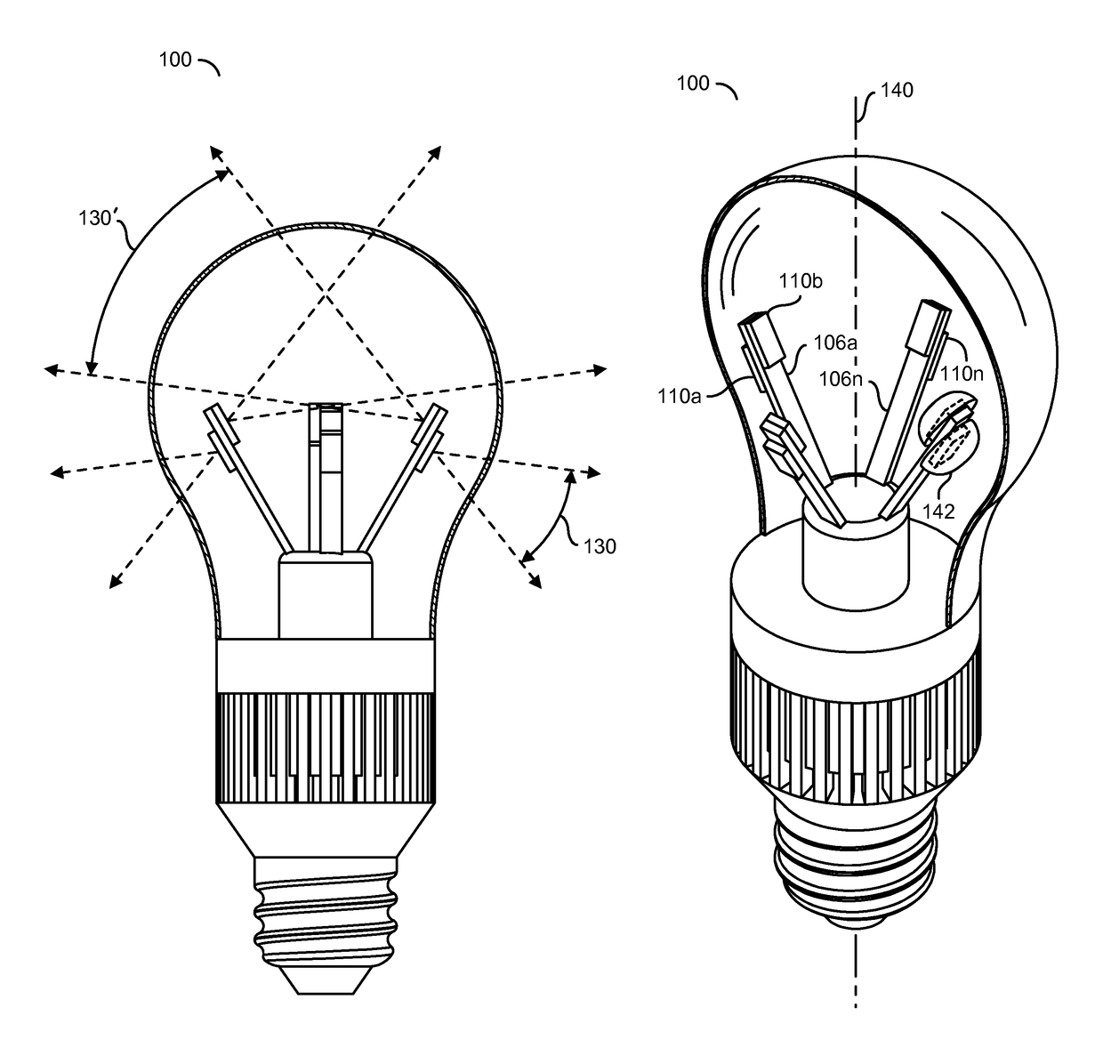
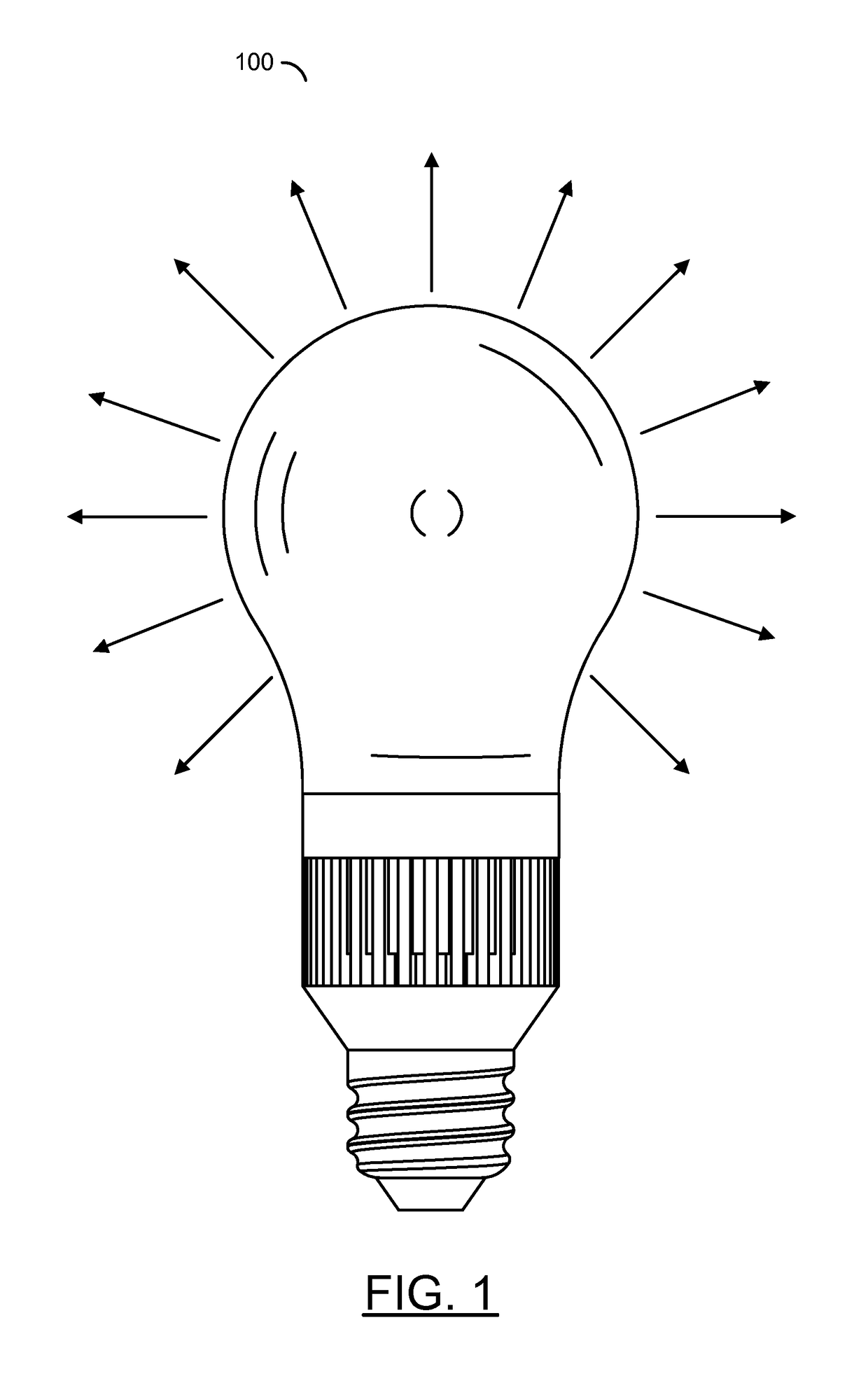
[0024]Referring to FIG. 1, a block diagram of a bulb 100 is shown in accordance with a preferred embodiment of the present invention. The bulb 100 may mount a number of LED elements to provide a uniform light distribution. The particular mounting may allow, in one example, a 290 degree light projection. The particular light projection pattern may be varied to meet the design criteria of a particular implementation. The bulb 100 may provide a unique feel of a centered light source (similar to old fashion incandescent lights) and / or provide a more uniform distribution of light.

[0025]The bulb 100 may be used in a variety of designs, such as lamps, ceiling fixtures, recessed lights, outdoor lights, etc. The bulb 100 may minimize the number of LED elements needed, while providing uniform light. In one example, 290 degrees of light may be projected. The bulb 100 may be used in the same manner as existing lights. With the LED energy efficiency of LED elements, a green experience may be imp...


PUM

PropertyMeasurementUnit
power consumptionaaaaaaaaaa

Abstract

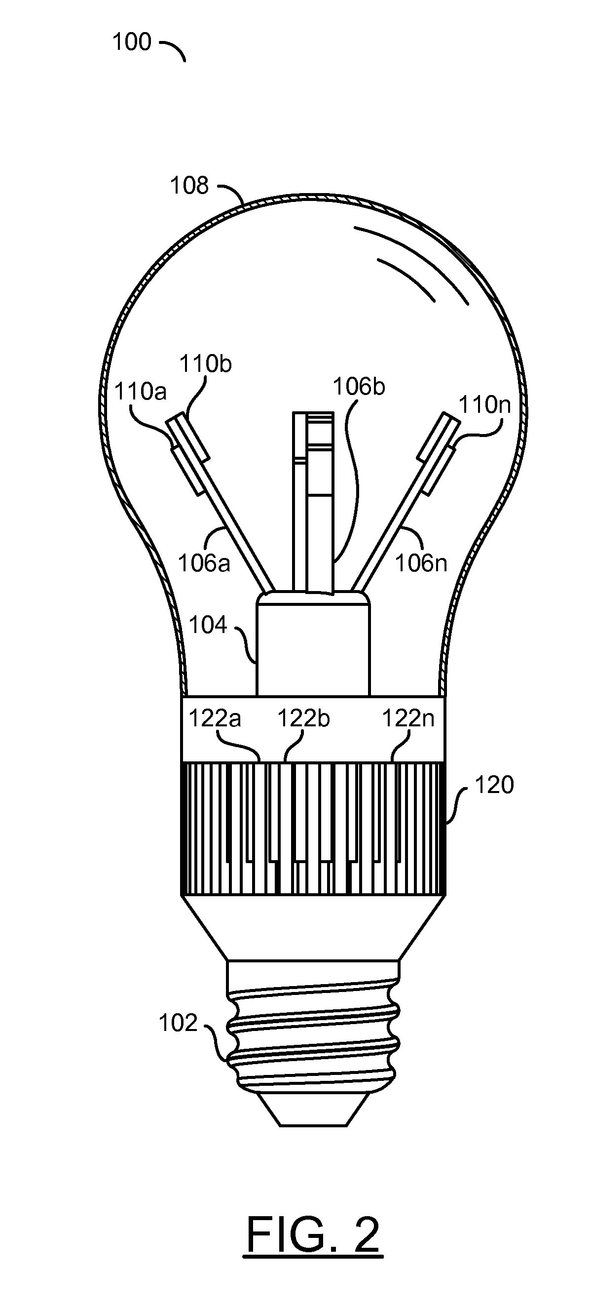
An apparatus comprising a base, a heat sink, a plurality of thermal elements, and a plurality of LED elements. The base may be configured to attach to a screw in light socket. The heat sink may be connected to the base. The plurality of thermal mounts may project from the heat sink. The thermal mounts may be electrically connected to the base and thermally connected to the heat sink. The plurality of LED elements may be connected to the thermal mounts. The LED elements may form a pattern about a central axis to project light evenly from the apparatus.

Description

[0001]This application relates to U.S. Ser. No. 13 / 870,208, filed Apr. 25, 2013, which relates to U.S. Provisional Application No. 61 / 782,844, filed Mar. 14, 2013 and U.S. Provisional Application No. 61 / 729,009, filed Nov. 21, 2012, each of which are hereby incorporated by reference in their entirety.FIELD OF THE INVENTION[0002]The present invention relates to lighting in general and, more particularly, to a method and / or architecture for implementing an LED lightbulb with a full light dispersion.BACKGROUND OF THE INVENTION[0003]Conventional incandescent light bulbs provide an even distribution of light. However, conventional incandescent light bulbs are inefficient when it comes to power consumption. Modern technologies, such as compact fluorescent bulbs (CFL) and light emitting diode (LED) bulbs improve the overall power efficiency. However, such designs tend to be aesthetically less pleasing than a conventional incandescent bulb.[0004]It would be desirable to implement a LED ligh...

Claims


Application Information

Patent Timeline
Patent Type & Authority Patents(United States)
IPC IPC(8): F21K9/232F21V29/70F21K99/00F21V23/00
CPCF21V23/003F21V29/70F21Y2101/02F21V29/74F21K9/232F21Y2115/10F21Y2107/00F21Y2101/00F21V3/062
Inventor PINATO, ROBERT M.
Owner PINATO ROBERT M
Learn More