Toner container, developing device, process cartridge, and image forming apparatus that include an operating member to move a shutter for a toner outlet via a linking member

a developing device and toner container technology, applied in the direction of sustainable packaging, electrographic process, instruments, etc., can solve the problems of difficult positioning of additional components while avoiding interference with other surrounding components, affecting the operation and preventing the toner from leaking through the outlet. , to achieve the effect of reducing the size of the image forming apparatus

Active Publication Date: 2017-06-27
RICOH KK
View PDF62 Cites 2 Cited by
  • Summary
  • Abstract
  • Description
  • Claims
  • Application Information

AI Technical Summary

Benefits of technology

[0009]According to an aspect of the present invention, in a state in which a container body is not mounted in a mounting portion, a shutter and an operating member are in a non-linked state with each other. Hence, even if an operator operates the operating member, the shutter does not open. As a result, it becomes possible to prevent the toner from leaking through an outlet. Moreover, since a linking member is configured to be able to perform a reciprocating linear movement, it can be configured in a compact manner thereby enabling downsizing. Besides, the operating member and the shutter can be made to operate in cooperation via the linking member which is compact in nature. Hence, it becomes possible to achieve downsizing of the image forming apparatus, as well as to provide a toner container that can be attached to the downsized image forming apparatus.

Problems solved by technology

However, regarding the toner cartridge disclosed in Patent Literature 1, in a state in which the toner cartridge is not mounted in the mounting portion; if a operator casually rotates the rotating knob, then there is a chance that the discharge port becomes open and the toner leaks out through the discharge port.
However, if a new component is to be added for that purpose, then there is a possibility that, from the perspective of the layout of components disposed in the main body of the developing device and in the toner container, positioning the additional component while avoiding interference with other surrounding components is a difficult task.
Particularly, as a result of the downsizing of devices that has occurred in recent years, in a configuration in which the components are disposed in a highly dense manner, it is difficult to secure space for disposing components.
Hence, it is all the more difficult to add a new component.

Method used


Image

  • Toner container, developing device, process cartridge, and image forming apparatus that include an operating member to move a shutter for a toner outlet via a linking member
  • Toner container, developing device, process cartridge, and image forming apparatus that include an operating member to move a shutter for a toner outlet via a linking member
  • Toner container, developing device, process cartridge, and image forming apparatus that include an operating member to move a shutter for a toner outlet via a linking member

Examples


Embodiment Construction

[0054]Given below is the explanation of the present invention with reference to the accompanying drawings. Herein, in the drawings used in explaining the present invention, regarding the constituent elements such as members or constituent components having the same function or the same shape, same reference numerals are used to a maximum extent of distinction and the explanation is not repeated after given once.

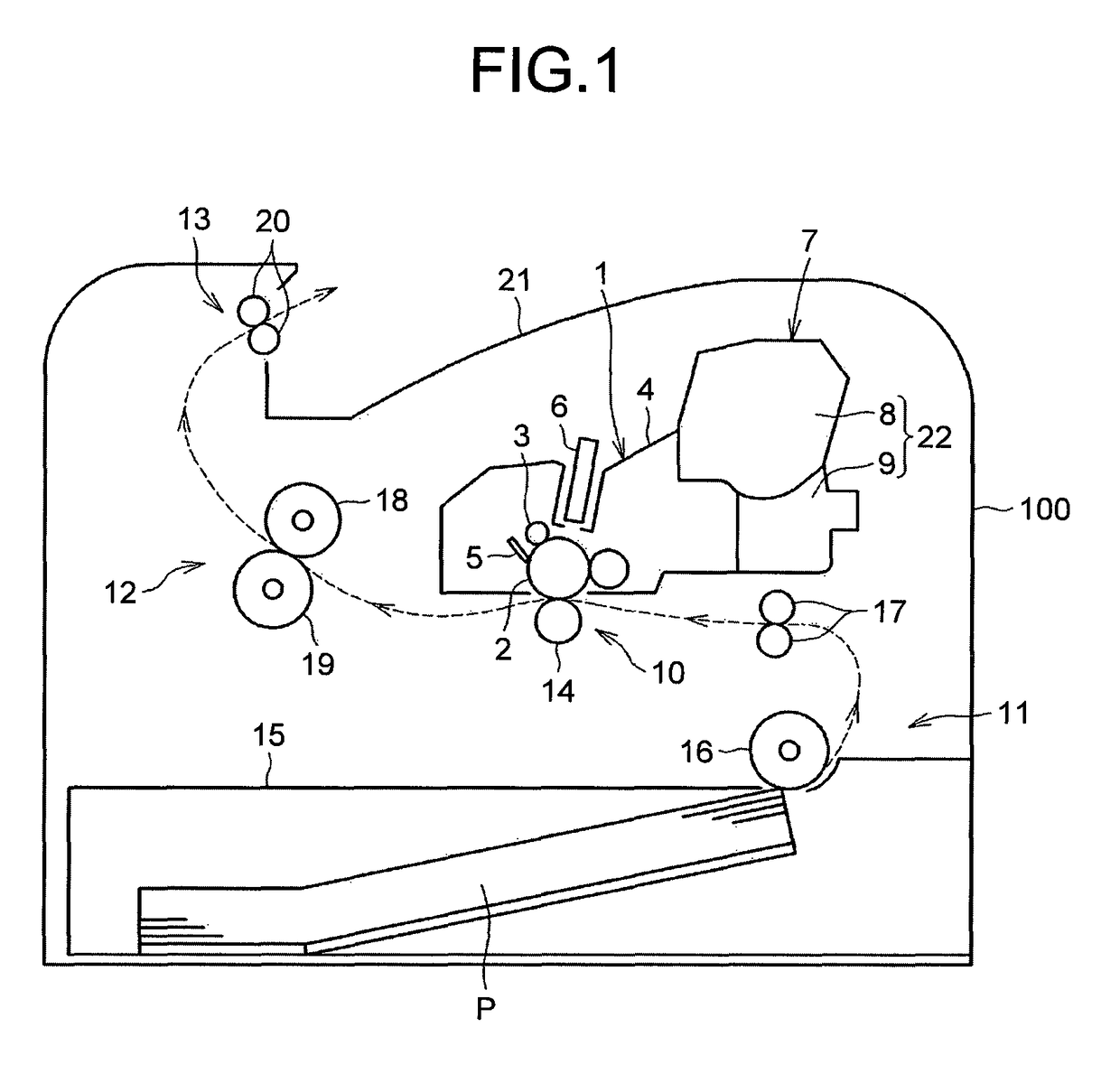
[0055]FIG. 1 is an overall configuration diagram illustrating an embodiment of an image forming apparatus. Firstly, explained below with reference to FIG. 1 is an overall configuration and operations of the image forming apparatus.

[0056]The image forming apparatus illustrated in FIG. 1 is a monochromatic image forming apparatus. In an apparatus main body (an image-forming-apparatus main body) 100, a process unit 1 functioning as an imaging unit is mounted in a detachable manner. The process unit 1 includes a photosensitive member 2 that functions as an image carrier for carry...


PUM


Abstract

A toner container includes a container body that is used to house a toner and that is detachably attachable to a mounting portion in a developing device; and an operating member that is used to open and close a shutter. The shutter as well as the operating member includes an engaging portion that can engage with a linking member which is disposed in the mounting portion and which can perform a reciprocating linear movement. In the state in which the container body is not mounted in the mounting portion, the shutter and the operating member are in a non-linked state with each other. In contrast, in the state in which the container body is mounted in the mounting portion, the shutter and the operating member become able to be linked to each other via the linking member.

Description

TECHNICAL FIELD[0001]The present invention is related to a toner container, a process cartridge to which the toner container can be detachably attached, and an image forming apparatus.BACKGROUND ART[0002]In an image forming apparatus such as a copying machine or a printer, it is a widely adopted method in which a toner container, which contains a toner for developing purposes, is configured to be detachably attachable to a developing device. In this method, when the toner container is attached to the developing device, a discharge port (an outlet) in the toner container gets connected to a supply port in the developing device, thereby enabling a supply of the toner from the toner container to the developing device. Typically, in such a type of the toner container, the discharge port is configured to be closable. With that, when the toner container is removed from the body of the developing device, the toner does not leak through the discharge port to the outside.[0003]For example, i...

Claims


Application Information

Patent Timeline
Patent Type & Authority Patents(United States)
IPC IPC(8): G03G15/08G03G21/18
CPCG03G15/0886G03G15/0865G03G21/1821G03G15/0875G03G2215/067G03G2221/1869Y02W30/80G03G15/08G03G2215/068
Inventor YOSHIDA, TOMOFUMISAKAYA, KOHTAARASAWA, SHINICHIPARK, JIN SAMJUNG, GOO CHULOGATA, YASUNOBU
Owner RICOH KK
Why Eureka
Try Eureka