Planar light source

a light source and planar technology, applied in the field of light sources, can solve problems such as increasing costs, and achieve the effect of reducing the quantity of led elements used and good light uniformity

Active Publication Date: 2017-07-11
CORETRONIC
View PDF54 Cites 11 Cited by
  • Summary
  • Abstract
  • Description
  • Claims
  • Application Information

AI Technical Summary

Benefits of technology

[0031]According to the above descriptions, the embodiment or embodiments of the invention have at least one of the following advantages, through the design of the first plane and the second plane of the prism portion and the design of the reflective surface, a light mixing distance and a light mixing effect of the light beam in the light guide plate are increased, which may effectively mitigate a problem of uneven light mixing and a hot spot issue of the conventional technique to obtain a planar light source having good light uniformity. Moreover, the quantity of the used LED elements is decreased, and it is unnecessary to add an additional light mixing area on the light guide plate, so that the planar light source of the invention satisfies the design requirement of slim border in application of the displays.

Problems solved by technology

The hot spots could be eliminated by decreasing the pitch P. However, when the pitch P is decreased, the manufacturer has to use more number of the LED elements 124, which increases the cost.

Method used


Image

  • Planar light source
  • Planar light source
  • Planar light source

Examples


first embodiment

[0048

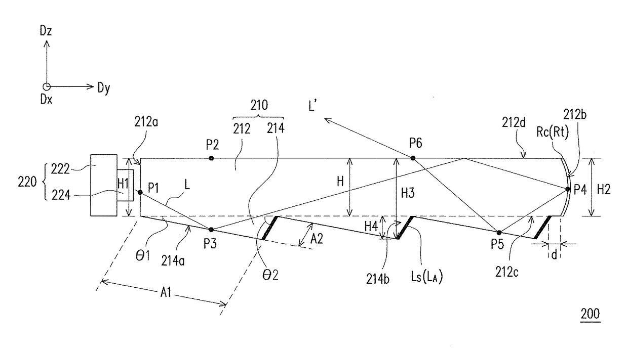
[0049]FIG. 3 is a cross-sectional view of a planar light source according to the first embodiment of the invention. Referring to FIG. 3, the planar light source 200 of the embodiment includes a light guide plate 210 and a light source device 220. The light guide plate 210 has a plate portion 212 and at least one prism portion 214 (a plurality of prism portions 214 shown in FIG. 3), wherein the plate portion 212 has a light incident surface 212a, a reflective surface 212b opposite to the light incident surface 212a, a bottom surface 212c, and a light exiting surface 212d opposite to the bottom surface 212c, wherein the light incident surface 212a and the reflective surface 212b are respectively connected to the bottom surface 212c and the light exiting surface 212d. The prism portions 214 are disposed on the bottom surface 212c of the plate portion 212, that is, the prism portions 214 are substantially adjacent to the bottom surface 212c of the plate portion 212, and each of the...

second embodiment

[0081

[0082]FIG. 6 is a cross-sectional view of a planar light source according to the second embodiment of the invention. Referring to FIG. 6, the planar light source 300 of the embodiment is similar to the planar light source 200 of the first embodiment, and a difference there between is that the reflective surface 312b of the embodiment applies a design similar to that of FIG. 5, and the light guide plate 210′ of the embodiment has a single prism portion 314, wherein the prism portion 314 has a first plane 314a and a second plane 314b, and a distance d between the second plane 314b and the reflective surface 312b is 0.

third embodiment

[0083

[0084]FIG. 7 is a cross-sectional view of a planar light source according to the third embodiment of the invention. Referring to FIG. 7, the planar light source 400 of the embodiment is similar to the planar light source 300 of the second embodiment, and a difference there between is that the light guide plate 210″ of the embodiment has a single prism portion 414, and the prism portion 414 has a first plane 414a and a second plane 414b, and the distance d between the second plane 414b and the reflective surface 412b is not equal to 0. For example, the length of the distance d is smaller than a length of the prism portion 414 on the bottom surface 212c along the direction Dy.


PUM


Abstract

A planar light source including a light guide plate (LGP) and a light source device is provided. The LGP includes a plate portion and at least one prism portion. The plate portion has a light incident surface, a reflective surface, a bottom surface, and a light exiting surface. The prism portion is disposed on the bottom surface of the plate portion, and has a first plane and a second plane. An included angle between the first plane and the bottom surface is smaller than an included angle between the second plane and the bottom surface, and a shortest distance between the first plane and the light incident surface is smaller than a shortest distance between the second plane and the light incident surface. The light source device is disposed adjacent to the light incident surface. The disclosure provides planar light source with good light uniformity.

Description

CROSS-REFERENCE TO RELATED APPLICATION[0001]This application claims the priority benefit of China application serial no. 201310243997.9, filed on Jun. 19, 2013. The entirety of the above-mentioned patent application is hereby incorporated by reference herein and made a part of this specification.BACKGROUND[0002]Technical Field[0003]The invention relates to a light source. Particularly, the invention relates to a planar light source.[0004]Related Art[0005]Since liquid crystal displays (LCDs) are non-self-luminous displays, a backlight module is required to provide required light to implement a display function. Along with enhancement of environmental awareness, light-emitting devices used in the backlight module are gradually changed from cold cathode fluorescent lamps (CCFLs) to more environmental friendly light-emitting diode (LED) elements. When the LED elements are applied to the backlight module, taking a side-light type backlight module as an example, the LED elements are gener...

Claims


Application Information

Patent Timeline
Patent Type & Authority Patents(United States)
IPC IPC(8): F21V8/00
CPCG02B6/0055G02B6/0038G02B6/0045G02B6/0036
Inventor WU, JHONG-HAOLIU, CHIN-KU
Owner CORETRONIC
Why Eureka
Try Eureka